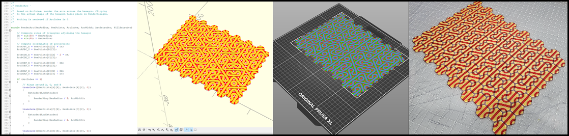
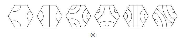
This repository contains OpenSCAD code to generate rectangular grids of hexagons in a form similar to those found in Kerry Mitchell's 2020 paper, Generalizations of Truchet Tiles. In that paper, Kerry presented a seemingly simple set of patterns that can be combined in pseudo-random or organized/structured ways to produce interesting patterns:
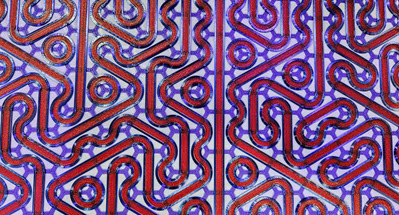
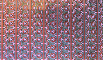
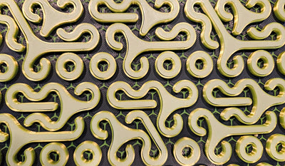
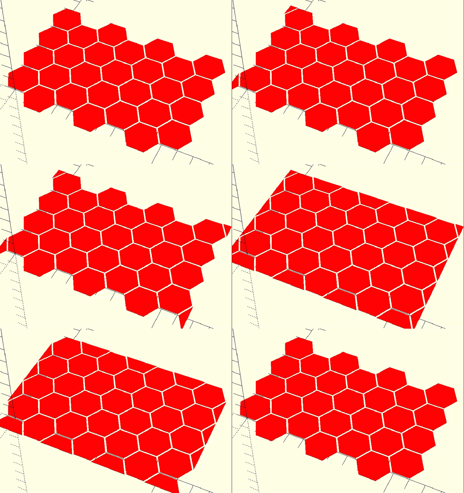
Here are a few examples of grids generated by this program and printed on a Prusa XL using 4 colors:
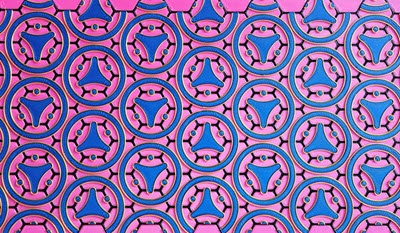
| TruchetMode(CircledTriad) | TruchetMode(3-4-5-6 + RandomSeed), Seed(131313) |
|---|---|
 | 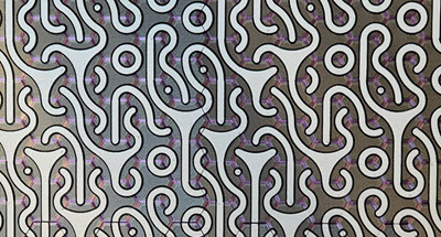 |
| TruchetMode(5),RotateFactor(7),RotateMod(3) | TruchetMode(LineCircleWave) |
 |  |
| TruchetMode(3-4-5-6 + FactorMod), Factor(4), Mod(3) | - |
 | - |
Here is an incomplete list of program features:
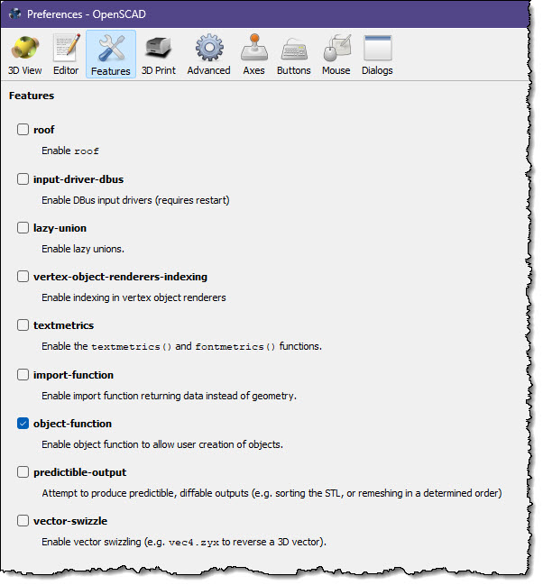
Install the latest nightly build of OpenSCAD, launch it, and then open the Preferences. Click on Features and check object-function:
Download hexagons_truchet.scad and open it in OpenSCAD. Make sure that the OpenSCAD Customizer is visible, and you are good to go. Simply make a change in the Customizer wait a second, and the display will update.
Now spend the next hour or two experimenting with the various options in the Customizer. When you are ready to create some STL files and slice them for printing, refer to the next section.
Important Sanity Tip: Before you get too far into this adventure, spend some time thinking about and implementing a naming scheme for your configurations, STL files, and GCODE files. If you are using the script below to create multiple mats to form a long and/or wide design, you will end up with 52 STL files per configuration. Good naming, and perhaps a log of your work, will be of immense value here.
After you have designed the grid of your dreams, you are ready to render, save, slice, and print it. To do this you use the WhichExtruder item in the Customizer:
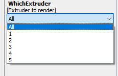
Set it to 1, press F6 (Render), wait for the render to finish, then press F7 to save the STL. Repeat this for each extruder. You will end up with four (at most) STL files.
Now go to your slicer and open all four of the STL files at the same time:
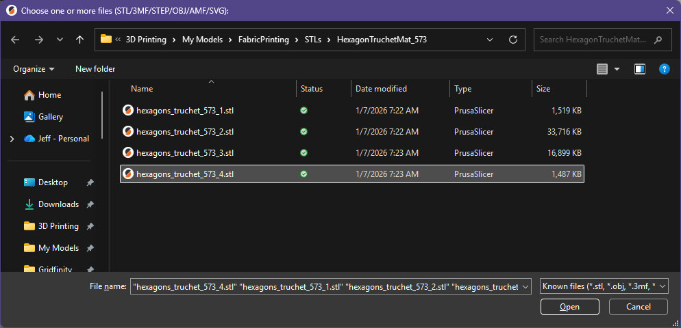
If you are using PrusaSlicer, answer Yes to this question:
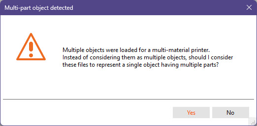
This will assign a unique extruder to each of the STL files:
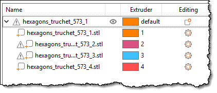
Slice, choose some amazing colors, and print!
Here is the overall flow:
flowchart LR
    A[Configuration]
    O[OpenSCAD]
    E1[Extruder 1 STL]
    E2[Extruder 2 STL]
    E3[Extruder 3 STL]
    E4[Extruder 4 STL]

    A --> O
    O --> |F6/F7| E1
    O --> |F6/F7| E2
    O --> |F6/F7| E3
    O --> |F6/F7| E4

    E1 --> Slicer
    E2 --> Slicer
    E3 --> Slicer
    E4 --> Slicer

    Slicer --> GCODE
    GCODE --> Printer
This section contains a description of each of the items in the Customizer. Once you start using this program in "production mode" and you need to be able to repeat and recall settings on demand, use OpenSCAD's preset menu (if you can figure out how it works :-)), take a screen shot of the Customizer, or capture this line in the Console output:
ECHO: { ArcExtruder = 2; ArcHeight = 0.2; ArcWidth = 1.4; CountX = 14; CountY = 17; EdgeExtruder = 4; EdgeHeight = 0.2; EdgeWidth = 1.2; FillExtruder = 3; Gap = 0; HexHeight = 0.4; HexRadius = 13; RandomSeed = 131313; Rotate = true; RotateFactor = 4; RotateMod = 3; TileExtruder = 1; TruchetMode = "5"; XYLabels = false; StartX = 0; LeftBorder = false; RightBorder = false; TopBorder = false; BottomBorder = false; TopLeftCorner = false; TopRightCorner = false; BottomLeftCorner = false; BottomRightCorner = false; }
All of the values in the Customizer are represented there. At some point there will be a way to turn this into a preset or a JSON file.
Experiment with all of the items and have a lot of fun as you do so.
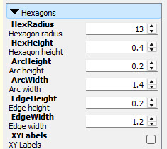
The values in this section control the size and other aspects of each hexagon:
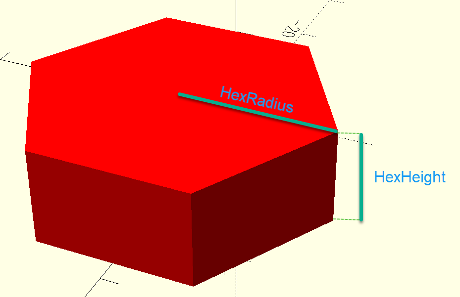
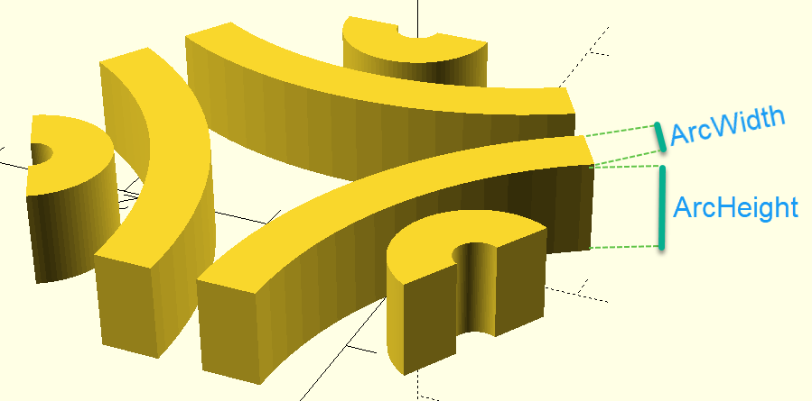
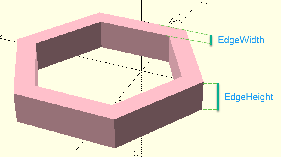
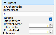
NB - RotateFactor and RotateMod are now more general than just for rotation, and will be renamed.
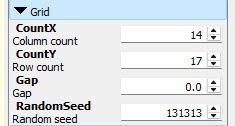
The values in this section control the overall size of the grid of hexagons:
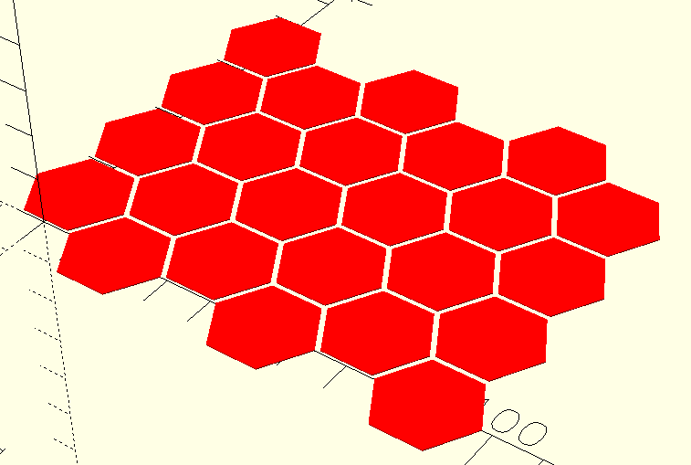
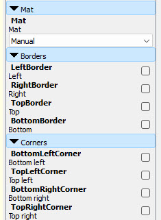
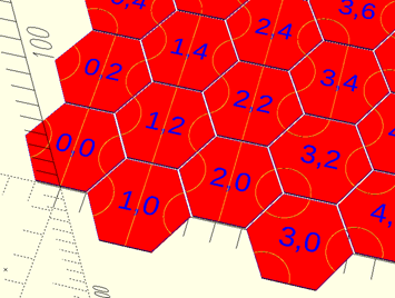
The values in this section control the borders and corners around the grid of hexagons. You can use the Mat to choose a predefined collection of settings that will make it easy for you to tile multiple grids into a large mat, or you can set it to Manual and control the borders and corners yourself. In most case the first option is easier and preferable. See the section below, Creating Multi-Print Mats, to learn more.
Mat - Either Manual to enable use of the border and corner controls, or a value A through M to specify a collection of border and corner settings.
LeftBorder - Enables a border on the left side if set.
RightBorder - Enables a border on the right side if set.
TopBorder - Enables a border on the top edge if set.
BottomBorder - Enables a border on the bottom edge if set.
BottomLeftCorner - Enables a corner on the bottom left if set.
TopLeftCorner - Enables a corner on the top left if set.
BottomRightCorner - Enables a corner on the bottom right if set.
TopRightCorner - Enables a corner on the top right if set.
Important Safety Tip: The borders and corners only work properly when CountX is odd and CountY is even.
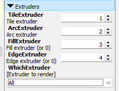
This section lets you create prints that work on multi-color / multi-filament printers. Set WhichExtruder to All while you are building your grid. Set the four other extruder values as desired (generally keeping them as 1-4 is fine). You can set FillExtruder and/or EdgeExtruder to 0 if you don't want these elements in your print.
This feature allows you to easily and efficiently create grids that have the proper combination of borders and edges to seamlessless connect to form arbitrarily long and/or wide mats. There are 13 different settings for Mat (A through M):
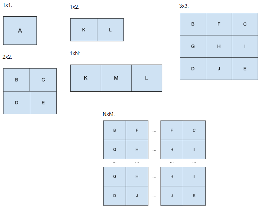
To use this feature, you design your grid as usual, then select one of the Mat values, render for each extruder, and proceed as usual. This will create a lot of files and is very tedious. Fortunately, the next section describes a tool that takes care of all of the repetitive work for you.
render_hexaxgons_truchet.bat in this repo simplifies the process of generating all of the STLs files neded to create a mat. It needs to be hand-edited to set the PARAM and PMAT values, and to be run in a specific directory two levels deeper than where the OpenSCAD file lives. Read the comments in the file to learn more and feel free to make this tool better.
flowchart LR
    PARAM[PARAM - OpenSCAD param file]
    PMAT[PMAT - Settings reference in PARAM]
    O[OpenSCAD]
    B[render_hexagons_truchet.bat]
    OUTFILE[OUTFILE - Directory for STLs]
    PARAM --> B
    PMAT --> B
    O --> B
    B --> OUTFILE
Here's what I am working on or thinking about working on:
If you use this code to create something cool, please reference this page and tag me on social media:
Here are some places to learn more about Truchet and his tiles:
203 followers · starred Jan 2026
76 followers · starred Jan 2026
This repository contains OpenSCAD code to generate rectangular grids of hexagons in a form similar to those found in Kerry Mitchell's 2020 paper, Generalizations of Truchet Tiles. In that paper, Kerry presented a seemingly simple set of patterns that can be combined in pseudo-random or organized/structured ways to produce interesting patterns:
Here are a few examples of grids generated by this program and printed on a Prusa XL using 4 colors:
| TruchetMode(CircledTriad) | TruchetMode(3-4-5-6 + RandomSeed), Seed(131313) |
|---|---|
| |
| TruchetMode(5),RotateFactor(7),RotateMod(3) | TruchetMode(LineCircleWave) |
| |
| TruchetMode(3-4-5-6 + FactorMod), Factor(4), Mod(3) | - |
| - |
Here is an incomplete list of program features:
Install the latest nightly build of OpenSCAD, launch it, and then open the Preferences. Click on Features and check object-function:
Download hexagons_truchet.scad and open it in OpenSCAD. Make sure that the OpenSCAD Customizer is visible, and you are good to go. Simply make a change in the Customizer wait a second, and the display will update.
Now spend the next hour or two experimenting with the various options in the Customizer. When you are ready to create some STL files and slice them for printing, refer to the next section.
Important Sanity Tip: Before you get too far into this adventure, spend some time thinking about and implementing a naming scheme for your configurations, STL files, and GCODE files. If you are using the script below to create multiple mats to form a long and/or wide design, you will end up with 52 STL files per configuration. Good naming, and perhaps a log of your work, will be of immense value here.
After you have designed the grid of your dreams, you are ready to render, save, slice, and print it. To do this you use the WhichExtruder item in the Customizer:
Set it to 1, press F6 (Render), wait for the render to finish, then press F7 to save the STL. Repeat this for each extruder. You will end up with four (at most) STL files.
Now go to your slicer and open all four of the STL files at the same time:
If you are using PrusaSlicer, answer Yes to this question:
This will assign a unique extruder to each of the STL files:
Slice, choose some amazing colors, and print!
Here is the overall flow:
flowchart LR
    A[Configuration]
    O[OpenSCAD]
    E1[Extruder 1 STL]
    E2[Extruder 2 STL]
    E3[Extruder 3 STL]
    E4[Extruder 4 STL]

    A --> O
    O --> |F6/F7| E1
    O --> |F6/F7| E2
    O --> |F6/F7| E3
    O --> |F6/F7| E4

    E1 --> Slicer
    E2 --> Slicer
    E3 --> Slicer
    E4 --> Slicer

    Slicer --> GCODE
    GCODE --> Printer
This section contains a description of each of the items in the Customizer. Once you start using this program in "production mode" and you need to be able to repeat and recall settings on demand, use OpenSCAD's preset menu (if you can figure out how it works :-)), take a screen shot of the Customizer, or capture this line in the Console output:
ECHO: { ArcExtruder = 2; ArcHeight = 0.2; ArcWidth = 1.4; CountX = 14; CountY = 17; EdgeExtruder = 4; EdgeHeight = 0.2; EdgeWidth = 1.2; FillExtruder = 3; Gap = 0; HexHeight = 0.4; HexRadius = 13; RandomSeed = 131313; Rotate = true; RotateFactor = 4; RotateMod = 3; TileExtruder = 1; TruchetMode = "5"; XYLabels = false; StartX = 0; LeftBorder = false; RightBorder = false; TopBorder = false; BottomBorder = false; TopLeftCorner = false; TopRightCorner = false; BottomLeftCorner = false; BottomRightCorner = false; }
All of the values in the Customizer are represented there. At some point there will be a way to turn this into a preset or a JSON file.
Experiment with all of the items and have a lot of fun as you do so.
The values in this section control the size and other aspects of each hexagon:
NB - RotateFactor and RotateMod are now more general than just for rotation, and will be renamed.
The values in this section control the overall size of the grid of hexagons:
The values in this section control the borders and corners around the grid of hexagons. You can use the Mat to choose a predefined collection of settings that will make it easy for you to tile multiple grids into a large mat, or you can set it to Manual and control the borders and corners yourself. In most case the first option is easier and preferable. See the section below, Creating Multi-Print Mats, to learn more.
Mat - Either Manual to enable use of the border and corner controls, or a value A through M to specify a collection of border and corner settings.
LeftBorder - Enables a border on the left side if set.
RightBorder - Enables a border on the right side if set.
TopBorder - Enables a border on the top edge if set.
BottomBorder - Enables a border on the bottom edge if set.
BottomLeftCorner - Enables a corner on the bottom left if set.
TopLeftCorner - Enables a corner on the top left if set.
BottomRightCorner - Enables a corner on the bottom right if set.
TopRightCorner - Enables a corner on the top right if set.
Important Safety Tip: The borders and corners only work properly when CountX is odd and CountY is even.
This section lets you create prints that work on multi-color / multi-filament printers. Set WhichExtruder to All while you are building your grid. Set the four other extruder values as desired (generally keeping them as 1-4 is fine). You can set FillExtruder and/or EdgeExtruder to 0 if you don't want these elements in your print.
This feature allows you to easily and efficiently create grids that have the proper combination of borders and edges to seamlessless connect to form arbitrarily long and/or wide mats. There are 13 different settings for Mat (A through M):
To use this feature, you design your grid as usual, then select one of the Mat values, render for each extruder, and proceed as usual. This will create a lot of files and is very tedious. Fortunately, the next section describes a tool that takes care of all of the repetitive work for you.
render_hexaxgons_truchet.bat in this repo simplifies the process of generating all of the STLs files neded to create a mat. It needs to be hand-edited to set the PARAM and PMAT values, and to be run in a specific directory two levels deeper than where the OpenSCAD file lives. Read the comments in the file to learn more and feel free to make this tool better.
flowchart LR
    PARAM[PARAM - OpenSCAD param file]
    PMAT[PMAT - Settings reference in PARAM]
    O[OpenSCAD]
    B[render_hexagons_truchet.bat]
    OUTFILE[OUTFILE - Directory for STLs]
    PARAM --> B
    PMAT --> B
    O --> B
    B --> OUTFILE
Here's what I am working on or thinking about working on:
If you use this code to create something cool, please reference this page and tag me on social media:
Here are some places to learn more about Truchet and his tiles:
203 followers · starred Jan 2026
76 followers · starred Jan 2026