Browser-based tool that turns a PCB photo into a printable 3D holder (STL) for hand-soldering THT parts. No signup, no upload, works offline.
See the code
3D STL file generator for THT PCB panels, online access: https://segmentcontroller.github.io/pcb-tht-holder/
I make almost all of my printed circuit boards with online design software and entrust the manufacturing company to install the SMD components. I install the THT (through hole technology) components at home for two reasons:
I would also like to do the THT installation at home nicely. However, with many panels there are "traces of haste".
In its current state, it facilitates the installation of circular and oblong components. This is sufficient in the following cases: relays, capacitors, resistors, terminals and pin-headers. It automatically calculates the required area and volume based on the height of the parts. But it doesn't mean that there aren't any mistakes in it: if you experience anything, I welcome your comments.
M to measure distances in 1/10th millimeter precision+ / - / * keys, or Ctrl/Cmd + mouse wheel (trackpad pinch)
Ctrl+Z to undo operations (max 50 actions)
R key) and dimension flip (F key)P - Pointer mode (select and move elements)M - Measure mode (measure distances on PCB)Shift+C - Add new circleShift+R - Add new rectangleShift+L - Add new support legArrow keys - Fine move 0.1mmShift+Arrow keys - Move 0.5mm (5x faster)R - Rotate +5°Shift+R - Reset rotation to 0°F - Flip dimensions (swap width/height)Arrow keys / Home / End to navigate it and ESC to close it+ / - - Zoom in / out by 10%* - Reset zoom to 100%Ctrl+Wheel / Cmd+Wheel / trackpad pinch - Zoom at the cursorCtrl+Z / Cmd+Z - Undo last operation (deletions, property edits, rotations, flips)Shift+P - Project settingsD - Display 3D meshESC - Close modal dialogsDouble-click - Edit element propertiesClick here: https://segmentcontroller.github.io/pcb-tht-holder/
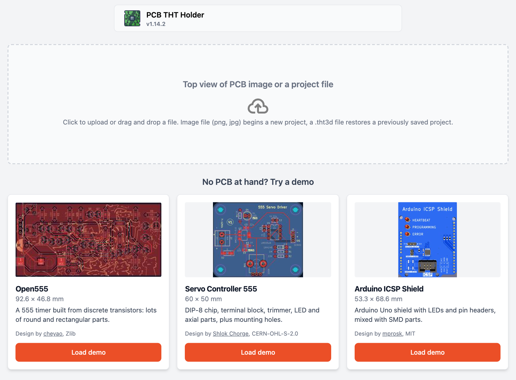
Enter a PCB image with drag and drop or file selection, which will automatically flip and become transparent.
No PCB at hand? Pick one of the three demo boards under the dropzone: it loads a ready-made project with its holes and support legs already placed. Demo credits and licences: public/demo/CREDITS.md.
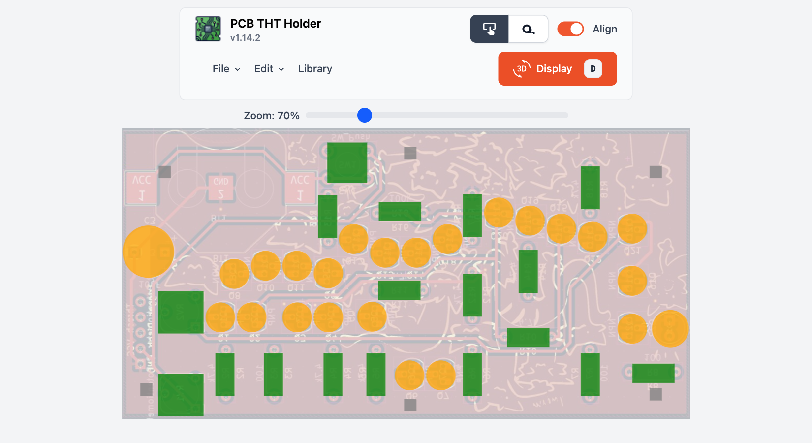
Place the THT parts by placing circles or squares. Adjust their height/depth exactly so that they are flush with the PCB. At the end, if necessary, add legs to support the PCB.
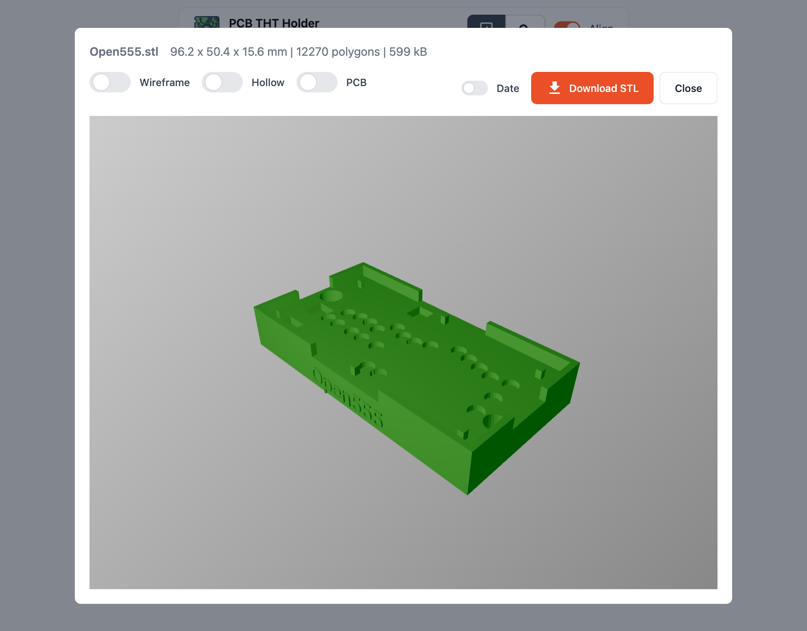
Click the Display 3D button and see the generated mesh. Rotate it, check that all components are in place. At the end, download the STL file (binary format).
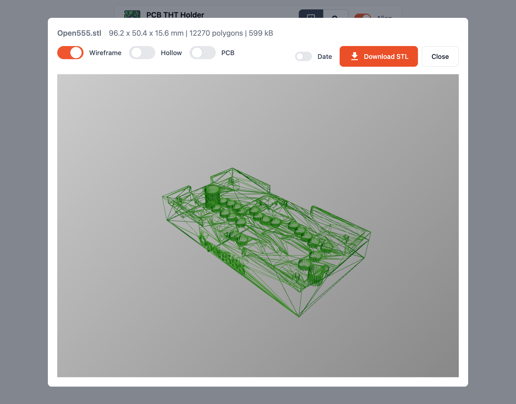
If you want to analyze the location of the components, you can also see how things fit in the wireframe view.
Use a PLA printer to save time and money. Practice shows that it is enough to produce the STL file once, of which 1-3 prints are enough to implant hundreds of PCBs.
$props(), $state(), $derived())@tailwindcss/vite)*.test.ts)# Install dependencies
npm install
# Start development server (accessible on network)
npm run dev
# Run unit tests (Vitest)
npm run test
# Run tests in watch mode
npm run test:watch
# Run type checking
npm run ts:check
# Run linting
npm run lint:check
# Format code
npm run format:fix
# Build for production
npm run build
# Run all checks (format, lint, types, tests) and build
npm run all
src/ - Source code
components/ - Svelte componentslib/ - Utility functions and 3D generation logic (lib/3d/ runs CSG in a Web Worker and repairs the result into a watertight mesh)stores/ - Svelte stores for state managementtypes/ - TypeScript type definitions and Zod schemaspublic/ - Static assetsdocs/ - Production build output (GitHub Pages)See CHANGELOG.md for recent changes and version history.
Browser-based tool that turns a PCB photo into a printable 3D holder (STL) for hand-soldering THT parts. No signup, no upload, works offline.
See the code
3D STL file generator for THT PCB panels, online access: https://segmentcontroller.github.io/pcb-tht-holder/
I make almost all of my printed circuit boards with online design software and entrust the manufacturing company to install the SMD components. I install the THT (through hole technology) components at home for two reasons:
I would also like to do the THT installation at home nicely. However, with many panels there are "traces of haste".
In its current state, it facilitates the installation of circular and oblong components. This is sufficient in the following cases: relays, capacitors, resistors, terminals and pin-headers. It automatically calculates the required area and volume based on the height of the parts. But it doesn't mean that there aren't any mistakes in it: if you experience anything, I welcome your comments.
M to measure distances in 1/10th millimeter precision+ / - / * keys, or Ctrl/Cmd + mouse wheel (trackpad pinch)
Ctrl+Z to undo operations (max 50 actions)
R key) and dimension flip (F key)P - Pointer mode (select and move elements)M - Measure mode (measure distances on PCB)Shift+C - Add new circleShift+R - Add new rectangleShift+L - Add new support legArrow keys - Fine move 0.1mmShift+Arrow keys - Move 0.5mm (5x faster)R - Rotate +5°Shift+R - Reset rotation to 0°F - Flip dimensions (swap width/height)Arrow keys / Home / End to navigate it and ESC to close it+ / - - Zoom in / out by 10%* - Reset zoom to 100%Ctrl+Wheel / Cmd+Wheel / trackpad pinch - Zoom at the cursorCtrl+Z / Cmd+Z - Undo last operation (deletions, property edits, rotations, flips)Shift+P - Project settingsD - Display 3D meshESC - Close modal dialogsDouble-click - Edit element propertiesClick here: https://segmentcontroller.github.io/pcb-tht-holder/
Enter a PCB image with drag and drop or file selection, which will automatically flip and become transparent.
No PCB at hand? Pick one of the three demo boards under the dropzone: it loads a ready-made project with its holes and support legs already placed. Demo credits and licences: public/demo/CREDITS.md.
Place the THT parts by placing circles or squares. Adjust their height/depth exactly so that they are flush with the PCB. At the end, if necessary, add legs to support the PCB.
Click the Display 3D button and see the generated mesh. Rotate it, check that all components are in place. At the end, download the STL file (binary format).
If you want to analyze the location of the components, you can also see how things fit in the wireframe view.
Use a PLA printer to save time and money. Practice shows that it is enough to produce the STL file once, of which 1-3 prints are enough to implant hundreds of PCBs.
$props(), $state(), $derived())@tailwindcss/vite)*.test.ts)# Install dependencies
npm install
# Start development server (accessible on network)
npm run dev
# Run unit tests (Vitest)
npm run test
# Run tests in watch mode
npm run test:watch
# Run type checking
npm run ts:check
# Run linting
npm run lint:check
# Format code
npm run format:fix
# Build for production
npm run build
# Run all checks (format, lint, types, tests) and build
npm run all
src/ - Source code
components/ - Svelte componentslib/ - Utility functions and 3D generation logic (lib/3d/ runs CSG in a Web Worker and repairs the result into a watertight mesh)stores/ - Svelte stores for state managementtypes/ - TypeScript type definitions and Zod schemaspublic/ - Static assetsdocs/ - Production build output (GitHub Pages)See CHANGELOG.md for recent changes and version history.