A practical hardware and software setup for a compact RL-powered biped robot.
Python
1,264
17 commits
updated Sep 11, 2026
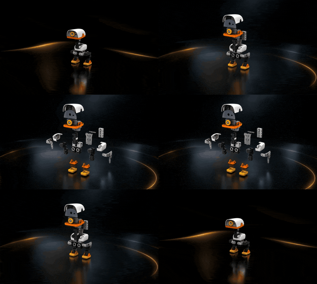
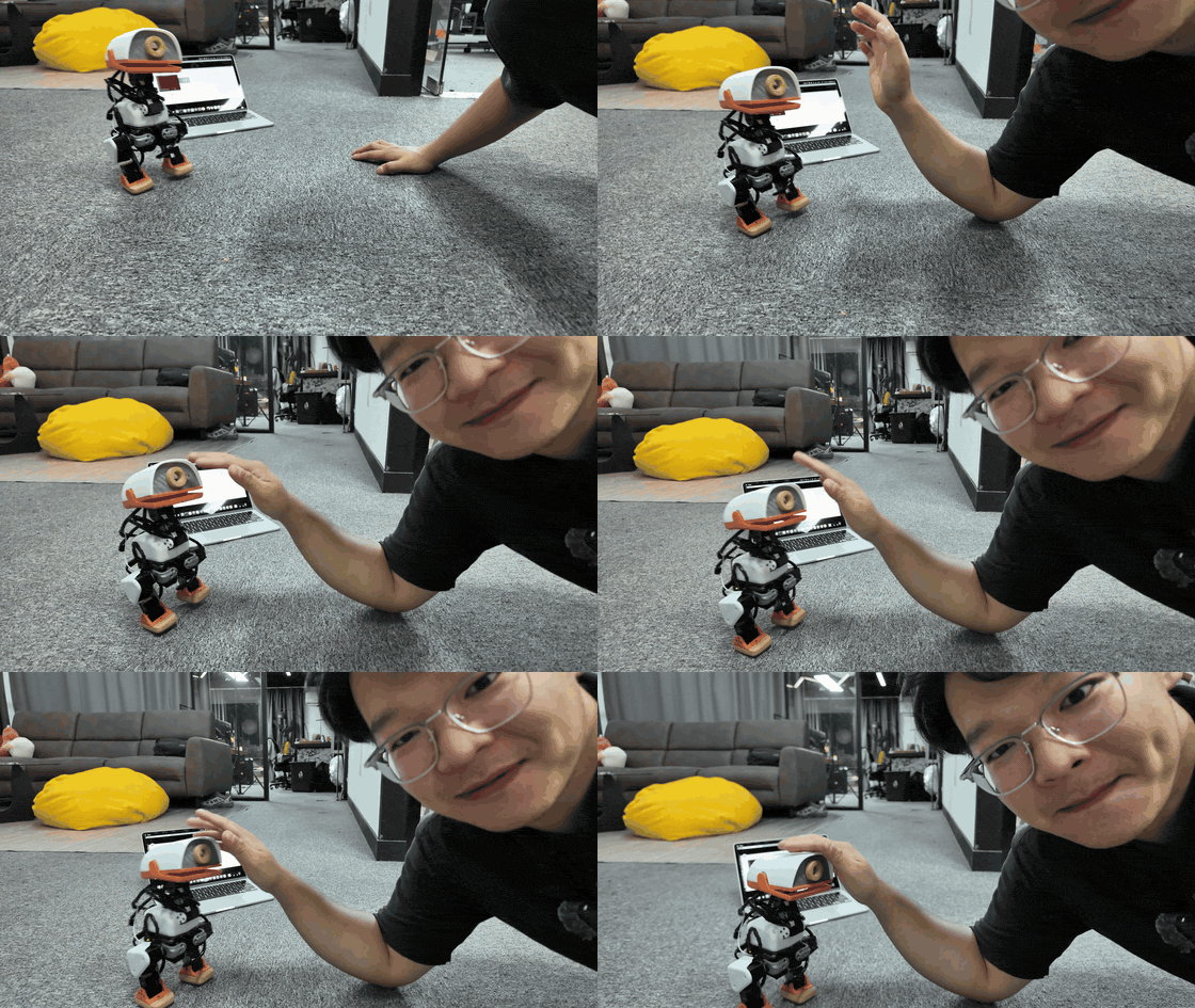
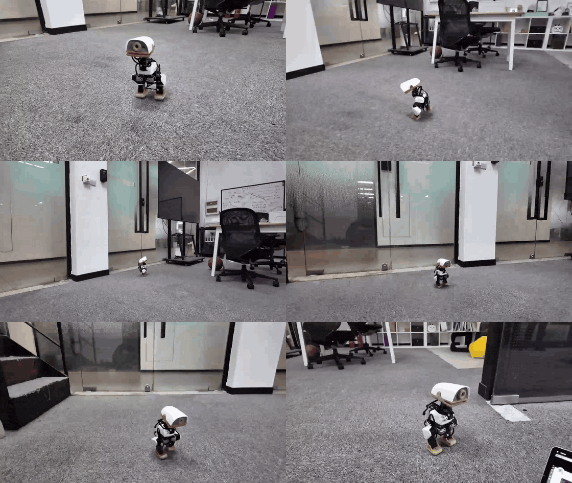
Microduck 是一个小型双足机器人项目,包含两部分:
microduck/: Raspberry Pi Zero 2 W 上运行的部署代码,负责读取 IMU、读取手柄/键盘输入、驱动 Dynamixel 舵机,并加载 ONNX 行走策略。mjlab_microduck/: 基于 MuJoCo/MjLab 的强化学习训练环境,用来训练并导出 walk.onnx。本 README 面向装机和第一次运行:准备硬件、接线、刷写 microduck.img.xz、初始化 Wi-Fi、SSH 登录、运行模型,以及后续更新代码。3D打印的文件在项目中。
视频教程:https://www.youtube.com/watch?v=Vep8AjoCnEM
感谢开源项目 microban 和 microduck。本项目的机械结构、部署思路、仿真训练和实机行走流程都受益于这些开源工作。
当前发布镜像已经内置:
microduck。user。~/microduck。~/microduck/.venv。~/microduck/src/agents/walk.onnx。microduck-gamepad.service,可开机后用手柄启动模型。当前预构建镜像:
下面是组装一台 Microduck 的主要物料。价格会随地区、采购渠道和批量变化,仅用于估算。
| 类别 | 物料 | 数量 | 说明 |
|---|---|---|---|
| 控制板 | Raspberry Pi Zero 2 W | 1 | 运行控制程序、蓝牙手柄、Wi-Fi 和 SSH。 |
| 舵机控制板 | ROBOTIS OpenRB-150 | 1 | 通过 USB 连接 Raspberry Pi,负责和 XL330 舵机总线通信。代码会优先自动查找 /dev/serial/by-id/usb-ROBOTIS_OpenRB-150_*。 |
| 舵机 | Dynamixel XL330-M288-T | 14 | 当前行走代码使用 14 个舵机:双腿 10 个,头/颈 4 个。若安装嘴部舵机,可使用 ID 15,但当前行走模型不依赖它。 |
| 电池 | 成品 6V 可充电电池 | 1 | 当前硬件直接使用成品 6V 电池包供电,不使用两节 18650 自制电池组。请确认电池能提供足够瞬时电流。 |
| 开关 | 电源开关 | 1 | 控制机器人主电源。 |
| 存储 | 16GB 或更大 microSD 卡 | 1 | 推荐使用质量稳定的新卡。镜像刷写后首次启动会自动扩展分区。 |
| IMU | BNO080/BNO085/BNO086 模块 | 1 | 通过 I2C 读取姿态,代码会自动探测常见地址。 |
| 结构件 | 3D 打印件 | 1 套 | 使用 microduck/cad/ 中的模型打印。推荐 PLA。 |
| 螺丝 | M2/M2.5 自攻螺丝 | 若干 | 舵机固定、舵盘固定、结构件连接。建议多备。 |
| 线材 | Dynamixel 3-pin 线 | 若干 | 舵机串联、电源连接、分线。 |
控制代码期望的 ID 映射如下。烧录镜像之前或第一次运行之前,应先用 Dynamixel Wizard 设置好每个舵机。
| ID | 名称 | 位置 |
|---|---|---|
| 1 | right_ankle | 右踝 |
| 2 | right_knee | 右膝 |
| 3 | right_hip_pitch | 右髋俯仰 |
| 4 | right_hip_roll | 右髋横滚 |
| 5 | right_hip_yaw | 右髋偏航 |
| 6 | left_ankle | 左踝 |
| 7 | left_knee | 左膝 |
| 8 | left_hip_pitch | 左髋俯仰 |
| 9 | left_hip_roll | 左髋横滚 |
| 10 | left_hip_yaw | 左髋偏航 |
| 11 | head_pitch | 头部俯仰 |
| 12 | neck_pitch | 颈部俯仰 |
| 13 | head_yaw | 头部偏航 |
| 14 | head_roll | 头部横滚 |
| 15 | mouth | 可选嘴部舵机,当前行走策略不使用 |
Dynamixel Wizard 推荐参数:
2.01Mbps0255电源链路如下:
flowchart LR
    BAT[成品 6V 可充电电池] --> SW[电源开关]
    SW --> OPENRB[OpenRB-150 电源输入]
    OPENRB --> BUS[XL330 舵机总线]
    PI[Raspberry Pi Zero 2 W] -->|USB 数据线| OPENRB
    BAT --> REG[5V 稳压/USB 供电]
    REG --> PI
检查要点:
XL330 使用 3-pin 串联总线。OpenRB-150 接出后可通过分线分到左右腿和头部。
flowchart TD
    OPENRB[OpenRB-150 Dynamixel Port]
    OPENRB --> SPLIT[分线]
    SPLIT --> R5[右腿链: ID 5 -> 4 -> 3 -> 2 -> 1]
    SPLIT --> L10[左腿链: ID 10 -> 9 -> 8 -> 7 -> 6]
    SPLIT --> H12[头颈链: ID 12 -> 11 -> 13 -> 14]
注意:
/dev/ttyACM0、/dev/serial0、/dev/ttyAMA0 或 /dev/ttyS0。BNO08x 模块走 I2C:
| IMU 引脚 | Raspberry Pi / Hat |
|---|---|
VIN / 3V3 | 3.3V,按模块标识选择 |
GND | GND |
SDA | GPIO2 / I2C SDA |
SCL | GPIO3 / I2C SCL |
软件默认使用 I2C bus 1,会自动寻找 BNO08x 常见地址。安装方向由 IMU_MOUNT_QUAT 配置,已经和当前行走模型匹配。
microduck.img.xz下载或拷贝镜像后,建议先校验:
sha256sum microduck.img.xz
应与发布页面或上文给出的 SHA256 一致。
推荐使用 Raspberry Pi Imager:
Choose Device 选择 Raspberry Pi Zero 2 W。Choose OS 选择 Use custom,选中 microduck.img.xz。Choose Storage 选择目标 microSD 卡。No。Write,等待写入和验证完成。Linux 命令行也可以刷写,但要非常确认设备名:
lsblk
xzcat microduck.img.xz | sudo dd of=/dev/sdX bs=4M status=progress conv=fsync
把 /dev/sdX 换成你的 SD 卡设备,不要写成电脑硬盘。
两种方法任选其一。Pi Zero 2 W 只支持 2.4GHz Wi-Fi,不要使用纯 5GHz 网络。
刷写完成后,拔下再插回 SD 卡。Ubuntu 通常会挂载出两个分区:
bootfs: 启动分区,可直接编辑 Wi-Fi 配置。rootfs: 系统根分区,一般不需要手动改。编辑:
sudo nano /media/$USER/bootfs/network-config
内容类似:
network:
  version: 2
  ethernets:
    eth0:
      dhcp4: true
      dhcp6: true
      optional: true
  wifis:
    wlan0:
      dhcp4: true
      regulatory-domain: "<YOUR_COUNTRY_CODE>"
      access-points:
        "<YOUR_WIFI_NAME>":
          password: "<YOUR_WIFI_PASSWORD>"
      optional: true
把三处占位符改掉:
<YOUR_COUNTRY_CODE>: 两位国家/地区代码,例如 CN、US、GB、FR。<YOUR_WIFI_NAME>: Wi-Fi 名称。<YOUR_WIFI_PASSWORD>: Wi-Fi 密码。可配置多个 Wi-Fi:
      access-points:
        "HomeWifi":
          password: "home-password"
        "PhoneHotspot":
          password: "hotspot-password"
保存后安全弹出 SD 卡,插入机器人,打开电源。
刷写完成后把 SD 卡插入 Pi,接上 mini HDMI 显示器和 USB 键盘(Zero 需要 OTG 转接头)。镜像是 Raspberry Pi OS Lite,没有桌面,开机后是终端登录。
第一次启动会扩展分区,等待 1 到 3 分钟,不要断电。出现登录提示后:
用户名: user
密码:   password
输入密码时屏幕不会显示字符,直接回车。然后扫描并连接 Wi-Fi,设为开机自动连接:
nmcli device wifi list
sudo nmcli device wifi connect "你的WiFi名字" password "你的WiFi密码"
sudo nmcli con mod "你的WiFi名字" wifi.powersave disable
sudo nmcli con mod "你的WiFi名字" connection.autoconnect yes
检查是否连上、是否自动连接:
nmcli -t -f NAME,TYPE,AUTOCONNECT,DEVICE connection show
hostname -I
AUTOCONNECT 应为 yes,并且已经拿到 IP。之后每次开机都会自动连这个 Wi-Fi。
第一次启动会做几件事:
network-config 并连接 Wi-Fi(方法 1)。若用方法 2,首次启动后再用 nmcli 配置。等待 1 到 3 分钟,然后在电脑上测试:
ping microduck.local
如果 .local 解析失败,到路由器后台查看 Pi 的 IP,然后用 IP 登录。
默认登录:
ssh [email protected]
默认密码:
password
第一次登录后建议立刻改密码:
passwd
在电脑上远程登录 Pi。Windows 用 PowerShell,Linux / macOS 用终端:
ssh [email protected]
默认密码是 password。如果提示 REMOTE HOST IDENTIFICATION HAS CHANGED,先清掉旧记录再重连:
ssh-keygen -R microduck.local
登录成功后,把机器人放在稳定平面上或扶住,然后启动控制程序:
cd ~/microduck
PYTHONPATH=src .venv/bin/python src/main.py
启动后程序会:
src/agents/walk.onnx 行走策略。键盘控制:
| 按键 | 功能 |
|---|---|
v | 开启/关闭行走 |
| 方向键上/下 | 前进/后退 |
| 方向键左/右 | 左右转向 |
x | 速度归零 |
i | 显示/隐藏 IMU 信息 |
q | 停止控制循环 |
电脑和机器人连同一个 2.4GHz Wi-Fi 后,在 Windows PowerShell 或 Linux / macOS 终端执行:
ssh [email protected]
登录后:
cd ~/microduck
PYTHONPATH=src .venv/bin/python src/main.py
停止:按 q。如果程序还在跑,另开一个 SSH 窗口:
ssh [email protected]
cd ~/microduck
PYTHONPATH=src .venv/bin/python src/stop.py
安全关机:
ssh [email protected]
sudo shutdown -h now
不要直接断电。先关机,等 10 到 15 秒,再关闭电源开关。
SSH 到 Pi 后:
bluetoothctl
在 bluetoothctl 里执行:
power on
agent on
scan on
pair XX:XX:XX:XX:XX:XX
trust XX:XX:XX:XX:XX:XX
connect XX:XX:XX:XX:XX:XX
scan off
quit
把 XX:XX:XX:XX:XX:XX 换成扫描到的手柄 MAC 地址。
镜像里已经启用无头手柄服务。开机后:
| 操作 | 功能 |
|---|---|
按住 START 2 秒 | 启动控制循环 |
A | 开启/关闭行走 |
| 左摇杆 | 前后/左右速度 |
| 右摇杆左右 | 原地或行进中转向 |
B | 停止控制循环 |
| 同时按住左右扳机 2 秒 | 安全关机 |
手柄连接时,服务会关闭 Wi-Fi 以改善 2.4GHz 蓝牙稳定性。需要 SSH 时,先关闭手柄,Wi-Fi 会自动恢复。
在开发电脑的 microduck/ 目录下:
| 命令 | 说明 |
|---|---|
make sync | 同步本地部署代码到 Pi 的 ~/microduck。 |
make setup | 同步代码并在 Pi 上执行 uv sync --frozen。改依赖后使用。 |
make run | 同步并启动控制循环。 |
make stop | 停止控制循环。 |
make shutdown | 安全关闭 Pi。 |
make imu | 查看 IMU/gyro 数据。 |
make voltage | 查看舵机电压。 |
make voltage ID=2 | 查看指定舵机电压。 |
make gamepad-headless-enable | 安装并启用无头手柄服务。 |
make gamepad-headless-disable | 禁用无头手柄服务。 |
训练仓 mjlab_microduck/ 导出的 ONNX 模型应放到:
microduck/src/agents/walk.onnx
更新后同步:
cd microduck
make sync
下一次运行会加载新的 walk.onnx。
当 Pi 上的系统、依赖、服务和模型都确认可用后,可以把这张 SD 卡做成新的 microduck.img.xz。
推荐流程:
make run 或手柄无头运行。.img 文件。/etc/machine-id。bootfs/network-config 为占位模板。~/microduck/src/agents/walk.onnx、.venv、microduck-gamepad.service 都存在。microduck.img.xz。本仓库已有详细步骤:
microduck/docs/dev/clone_sd.md
.
├── README.md
├── microduck/
│   ├── Makefile
│   ├── src/
│   │   ├── main.py
│   │   ├── scheduler.py
│   │   ├── robot_controller.py
│   │   ├── imu_reader.py
│   │   ├── agents/walk.onnx
│   │   └── moves/walk.py
│   ├── systemd/
│   └── docs/
└── mjlab_microduck/
    ├── src/mjlab_microduck/
    └── logs/
microduck.local先等 1 到 3 分钟。仍找不到时:
network-config YAML 缩进没变(方法 1)。nmcli device wifi list 和 hostname -I 确认已连上 2.4GHz 并拿到 IP。ssh user@<IP> 登录。发布镜像首次启动会重新生成 SSH host keys。如果同一台电脑以前连过另一张卡,清理本机记录:
ssh-keygen -R microduck.local
ssh-keygen -R <IP>
检查:
这是无头模式的设计:手柄连接后会关闭 Wi-Fi,提升蓝牙稳定性。关闭手柄后 Wi-Fi 会恢复。
先手扶机器人运行,确认:
walk.onnx 是当前硬件对应的模型。make shutdown 或手柄安全关机。
Microduck is a compact biped robot project. This repository presents one practical hardware and software setup for running an ONNX reinforcement learning walking policy on real Dynamixel XL330 servos.
The project contains two main parts:
microduck/: deployment code for the Raspberry Pi Zero 2 W. It reads the IMU, reads keyboard or gamepad commands, drives Dynamixel servos, and loads the ONNX walking policy.mjlab_microduck/: reinforcement learning training environment based on MuJoCo/MjLab. It is used to train and export walk.onnx.This README covers the full first-time workflow: hardware, wiring, flashing microduck.img.xz, Wi-Fi setup, first SSH login, first run, day-to-day usage, and rebuilding a release image.
Thanks to the open-source projects microban and microduck. This project benefits from their mechanical design, deployment ideas, simulation training work, and real-robot walking pipeline.
The current release image includes:
microduck.user.~/microduck.~/microduck/.venv.~/microduck/src/agents/walk.onnx.microduck-gamepad.service, so the walking controller can be started from a gamepad after boot.Current prebuilt image:
SHA256:
096885dc32fb5b1db2ad69ba6bea868d8ab988f2b47c0d884eb63ba0dfdcb5c4
The following is the main bill of materials for building one Microduck. Prices vary by region, supplier, and quantity, so treat them as estimates.
| Category | Part | Qty | Notes |
|---|---|---|---|
| Main controller | Raspberry Pi Zero 2 W | 1 | Runs the control program, Bluetooth gamepad, Wi-Fi, and SSH. |
| Servo controller | ROBOTIS OpenRB-150 | 1 | Connected to the Raspberry Pi over USB. It communicates with the XL330 servo bus. The code first looks for /dev/serial/by-id/usb-ROBOTIS_OpenRB-150_*. |
| Servos | Dynamixel XL330-M288-T | 14 | The current walking code uses 14 servos: 10 for the legs and 4 for the head/neck. An optional mouth servo can use ID 15, but the walking policy does not depend on it. |
| Battery | Ready-made 6V rechargeable battery | 1 | This hardware setup uses a ready-made 6V battery pack, not a custom two-cell pack. Make sure the battery can provide enough peak current. |
| Switch | Power switch | 1 | Main power switch for the robot. |
| Storage | 16GB or larger microSD card | 1 | Use a reliable new card. The image expands the filesystem on first boot. |
| IMU | BNO080/BNO085/BNO086 module | 1 | Read over I2C. The code auto-detects common BNO08x addresses. |
| Mechanical parts | 3D-printed parts | 1 set | Print from the models under microduck/cad/. PLA is recommended. |
| Screws | M2/M2.5 self-tapping screws | Several | Used for servo mounting, horn mounting, and structural assembly. Keep extras. |
| Bearings/shims | POM shims and steel shims | Several | Low-cost rotational support. |
| Cables | Dynamixel 3-pin cables, JST wires, power connectors | Several | Servo daisy chains, power wiring, and splitters. |
| Setup tools | Dynamixel U2D2 + U2D2 Power Hub | 1 set | Used to configure servo IDs, baud rate, and parameters. One set can be shared across multiple robots. |
Recommended extras:
The deployment code expects the following ID mapping. Configure every servo with Dynamixel Wizard before the first run.
| ID | Name | Position |
|---|---|---|
| 1 | right_ankle | Right ankle |
| 2 | right_knee | Right knee |
| 3 | right_hip_pitch | Right hip pitch |
| 4 | right_hip_roll | Right hip roll |
| 5 | right_hip_yaw | Right hip yaw |
| 6 | left_ankle | Left ankle |
| 7 | left_knee | Left knee |
| 8 | left_hip_pitch | Left hip pitch |
| 9 | left_hip_roll | Left hip roll |
| 10 | left_hip_yaw | Left hip yaw |
| 11 | head_pitch | Head pitch |
| 12 | neck_pitch | Neck pitch |
| 13 | head_yaw | Head yaw |
| 14 | head_roll | Head roll |
| 15 | mouth | Optional mouth servo, not used by the current walking policy |
Recommended Dynamixel Wizard settings:
2.01Mbps0255The power path is:
flowchart LR
    BAT[Ready-made 6V rechargeable battery] --> SW[Power switch]
    SW --> OPENRB[OpenRB-150 power input]
    OPENRB --> BUS[XL330 servo bus]
    PI[Raspberry Pi Zero 2 W] -->|USB data cable| OPENRB
    BAT --> REG[5V regulator / USB power]
    REG --> PI
Checklist:
XL330 servos use a 3-pin daisy-chain bus. The OpenRB-150 output can be split into the right leg, left leg, and head/neck chains.
flowchart TD
    OPENRB[OpenRB-150 Dynamixel Port]
    OPENRB --> SPLIT[Splitter]
    SPLIT --> R5[Right leg chain: ID 5 -> 4 -> 3 -> 2 -> 1]
    SPLIT --> L10[Left leg chain: ID 10 -> 9 -> 8 -> 7 -> 6]
    SPLIT --> H12[Head/neck chain: ID 12 -> 11 -> 13 -> 14]
Notes:
/dev/ttyACM0, /dev/serial0, /dev/ttyAMA0, or /dev/ttyS0.The BNO08x module uses I2C:
| IMU Pin | Raspberry Pi / Hat |
|---|---|
VIN / 3V3 | 3.3V, depending on the module label |
GND | GND |
SDA | GPIO2 / I2C SDA |
SCL | GPIO3 / I2C SCL |
The software uses I2C bus 1 by default and auto-detects common BNO08x addresses. The mounting orientation is configured by IMU_MOUNT_QUAT, which is already matched to the current walking model.
microduck.img.xzAfter downloading or copying the image, verify it:
sha256sum microduck.img.xz
The result should match the SHA256 published with the image.
Raspberry Pi Imager is recommended:
Choose Device -> Raspberry Pi Zero 2 W.Choose OS -> Use custom, then choose microduck.img.xz.Choose Storage, then choose the target microSD card.No.Write and wait for writing and verification to complete.You can also flash from the Linux command line. Be very careful with the device name:
lsblk
xzcat microduck.img.xz | sudo dd of=/dev/sdX bs=4M status=progress conv=fsync
Replace /dev/sdX with your SD card device. Do not write to your computer's internal disk.
Use either method. The Raspberry Pi Zero 2 W only supports 2.4GHz Wi-Fi. Do not use a 5GHz-only network.
After flashing, unplug and reinsert the SD card. Ubuntu usually mounts two partitions:
bootfs: boot partition, where Wi-Fi can be configured.rootfs: root filesystem, usually no manual edits are needed.Edit:
sudo nano /media/$USER/bootfs/network-config
The file looks like this:
network:
  version: 2
  ethernets:
    eth0:
      dhcp4: true
      dhcp6: true
      optional: true
  wifis:
    wlan0:
      dhcp4: true
      regulatory-domain: "<YOUR_COUNTRY_CODE>"
      access-points:
        "<YOUR_WIFI_NAME>":
          password: "<YOUR_WIFI_PASSWORD>"
      optional: true
Replace:
<YOUR_COUNTRY_CODE>: two-letter country code, such as CN, US, GB, or FR.<YOUR_WIFI_NAME>: Wi-Fi name.<YOUR_WIFI_PASSWORD>: Wi-Fi password.Multiple Wi-Fi networks can be configured:
      access-points:
        "HomeWifi":
          password: "home-password"
        "PhoneHotspot":
          password: "hotspot-password"
Save the file, safely eject the SD card, insert it into the robot, and power on.
After flashing, insert the SD card into the Pi and connect a mini HDMI display plus a USB keyboard (the Zero needs a USB OTG adapter). The image is Raspberry Pi OS Lite, so there is no desktop — only a terminal login.
The first boot expands the partition. Wait 1 to 3 minutes and do not power off. When the login prompt appears:
username: user
password: password
The password is not echoed. Then scan, connect, and enable autoconnect:
nmcli device wifi list
sudo nmcli device wifi connect "YOUR_WIFI_NAME" password "YOUR_WIFI_PASSWORD"
sudo nmcli con mod "YOUR_WIFI_NAME" wifi.powersave disable
sudo nmcli con mod "YOUR_WIFI_NAME" connection.autoconnect yes
Check that it is connected and set to autoconnect:
nmcli -t -f NAME,TYPE,AUTOCONNECT,DEVICE connection show
hostname -I
AUTOCONNECT should be yes, and the Pi should have an IP address. After that, this Wi-Fi will connect automatically on every boot.
On first boot, the image will:
network-config and join Wi-Fi (method 1). If you use method 2, configure Wi-Fi with nmcli after the first boot.Wait 1 to 3 minutes, then test from your computer:
ping microduck.local
If .local does not resolve, check your router's DHCP client list and use the Pi's IP address.
Default login:
ssh [email protected]
Default password:
password
Change the password after the first login:
passwd
Log in to the Pi from a computer. Use PowerShell on Windows, or a terminal on Linux / macOS:
ssh [email protected]
The default password is password. If SSH says REMOTE HOST IDENTIFICATION HAS CHANGED, clear the old host key and try again:
ssh-keygen -R microduck.local
After login, place the robot on a stable surface or hold it, then start the control program:
cd ~/microduck
PYTHONPATH=src .venv/bin/python src/main.py
On startup, the program will:
src/agents/walk.onnx.Keyboard controls:
| Key | Action |
|---|---|
v | Toggle walking |
| Up/down arrows | Forward/backward |
| Left/right arrows | Turn left/right |
x | Zero velocity |
i | Show/hide IMU status |
q | Stop the control loop |
After the computer and the robot are on the same 2.4GHz Wi-Fi, run this in Windows PowerShell or a Linux / macOS terminal:
ssh [email protected]
Then:
cd ~/microduck
PYTHONPATH=src .venv/bin/python src/main.py
Stop with q. If the program is still running, open another SSH session:
ssh [email protected]
cd ~/microduck
PYTHONPATH=src .venv/bin/python src/stop.py
Safe shutdown:
ssh [email protected]
sudo shutdown -h now
Do not cut power directly. Shut the Pi down first, wait 10 to 15 seconds, then turn off the power switch.
SSH into the Pi, then run:
bluetoothctl
Inside bluetoothctl:
power on
agent on
scan on
pair XX:XX:XX:XX:XX:XX
trust XX:XX:XX:XX:XX:XX
connect XX:XX:XX:XX:XX:XX
scan off
quit
Replace XX:XX:XX:XX:XX:XX with the detected controller MAC address.
The image already enables the headless gamepad service. After boot:
| Action | Function |
|---|---|
Hold START for 2 seconds | Start the control loop |
A | Toggle walking |
| Left stick | Forward/backward and lateral velocity |
| Right stick left/right | Turning |
B | Stop the control loop |
| Hold both triggers for 2 seconds | Safe shutdown |
When the gamepad is connected, the service disables Wi-Fi to improve 2.4GHz Bluetooth stability. Turn off the controller when you need SSH; Wi-Fi will be restored automatically.
Run these from the microduck/ directory on your development computer:
| Command | Description |
|---|---|
make sync | Sync local deployment code to ~/microduck on the Pi. |
make setup | Sync code and run uv sync --frozen on the Pi. Use after dependency changes. |
make run | Sync and start the control loop. |
make stop | Stop the control loop. |
make shutdown | Safely shut down the Pi. |
make imu | Print IMU/gyro data. |
make voltage | Read servo voltage. |
make voltage ID=2 | Read voltage from a specific servo. |
make gamepad-headless-enable | Install and enable the headless gamepad service. |
make gamepad-headless-disable | Disable the headless gamepad service. |
The ONNX model exported from mjlab_microduck/ should be placed at:
microduck/src/agents/walk.onnx
Then sync:
cd microduck
make sync
The next run will load the new walk.onnx.
After the Pi system, dependencies, services, and model have been tested, the SD card can be turned into a new microduck.img.xz.
Recommended workflow:
make run or headless gamepad mode on the real robot..img file./etc/machine-id.bootfs/network-config to placeholder values.~/microduck/src/agents/walk.onnx, .venv, and microduck-gamepad.service exist.microduck.img.xz.Detailed steps are in:
microduck/docs/dev/clone_sd.md
.
├── README.md
├── microduck/
│   ├── Makefile
│   ├── src/
│   │   ├── main.py
│   │   ├── scheduler.py
│   │   ├── robot_controller.py
│   │   ├── imu_reader.py
│   │   ├── agents/walk.onnx
│   │   └── moves/walk.py
│   ├── systemd/
│   └── docs/
└── mjlab_microduck/
    ├── src/mjlab_microduck/
    └── logs/
microduck.local Cannot Be FoundWait 1 to 3 minutes first. If it still cannot be found:
network-config is unchanged (method 1).nmcli device wifi list and hostname -I on the Pi to confirm it joined 2.4GHz Wi-Fi and has an IP.ssh user@<IP>.The release image regenerates SSH host keys on first boot. If your computer previously connected to another card, clear the local entry:
ssh-keygen -R microduck.local
ssh-keygen -R <IP>
Check:
This is expected in headless mode. The service disables Wi-Fi when the gamepad is connected to improve Bluetooth stability. Turn off the controller and Wi-Fi will be restored.
Hold the robot first, then check:
walk.onnx matches the current hardware.make shutdown or the gamepad shutdown gesture first.227 followers · starred Sep 2026
210 followers · starred Sep 2026
25 followers · starred Sep 2026
424 followers · starred Sep 2026
A practical hardware and software setup for a compact RL-powered biped robot.
Python
1,264
17 commits
updated Sep 11, 2026
Microduck 是一个小型双足机器人项目,包含两部分:
microduck/: Raspberry Pi Zero 2 W 上运行的部署代码,负责读取 IMU、读取手柄/键盘输入、驱动 Dynamixel 舵机,并加载 ONNX 行走策略。mjlab_microduck/: 基于 MuJoCo/MjLab 的强化学习训练环境,用来训练并导出 walk.onnx。本 README 面向装机和第一次运行:准备硬件、接线、刷写 microduck.img.xz、初始化 Wi-Fi、SSH 登录、运行模型,以及后续更新代码。3D打印的文件在项目中。
视频教程:https://www.youtube.com/watch?v=Vep8AjoCnEM
感谢开源项目 microban 和 microduck。本项目的机械结构、部署思路、仿真训练和实机行走流程都受益于这些开源工作。
当前发布镜像已经内置:
microduck。user。~/microduck。~/microduck/.venv。~/microduck/src/agents/walk.onnx。microduck-gamepad.service,可开机后用手柄启动模型。当前预构建镜像:
下面是组装一台 Microduck 的主要物料。价格会随地区、采购渠道和批量变化,仅用于估算。
| 类别 | 物料 | 数量 | 说明 |
|---|---|---|---|
| 控制板 | Raspberry Pi Zero 2 W | 1 | 运行控制程序、蓝牙手柄、Wi-Fi 和 SSH。 |
| 舵机控制板 | ROBOTIS OpenRB-150 | 1 | 通过 USB 连接 Raspberry Pi,负责和 XL330 舵机总线通信。代码会优先自动查找 /dev/serial/by-id/usb-ROBOTIS_OpenRB-150_*。 |
| 舵机 | Dynamixel XL330-M288-T | 14 | 当前行走代码使用 14 个舵机:双腿 10 个,头/颈 4 个。若安装嘴部舵机,可使用 ID 15,但当前行走模型不依赖它。 |
| 电池 | 成品 6V 可充电电池 | 1 | 当前硬件直接使用成品 6V 电池包供电,不使用两节 18650 自制电池组。请确认电池能提供足够瞬时电流。 |
| 开关 | 电源开关 | 1 | 控制机器人主电源。 |
| 存储 | 16GB 或更大 microSD 卡 | 1 | 推荐使用质量稳定的新卡。镜像刷写后首次启动会自动扩展分区。 |
| IMU | BNO080/BNO085/BNO086 模块 | 1 | 通过 I2C 读取姿态,代码会自动探测常见地址。 |
| 结构件 | 3D 打印件 | 1 套 | 使用 microduck/cad/ 中的模型打印。推荐 PLA。 |
| 螺丝 | M2/M2.5 自攻螺丝 | 若干 | 舵机固定、舵盘固定、结构件连接。建议多备。 |
| 线材 | Dynamixel 3-pin 线 | 若干 | 舵机串联、电源连接、分线。 |
控制代码期望的 ID 映射如下。烧录镜像之前或第一次运行之前,应先用 Dynamixel Wizard 设置好每个舵机。
| ID | 名称 | 位置 |
|---|---|---|
| 1 | right_ankle | 右踝 |
| 2 | right_knee | 右膝 |
| 3 | right_hip_pitch | 右髋俯仰 |
| 4 | right_hip_roll | 右髋横滚 |
| 5 | right_hip_yaw | 右髋偏航 |
| 6 | left_ankle | 左踝 |
| 7 | left_knee | 左膝 |
| 8 | left_hip_pitch | 左髋俯仰 |
| 9 | left_hip_roll | 左髋横滚 |
| 10 | left_hip_yaw | 左髋偏航 |
| 11 | head_pitch | 头部俯仰 |
| 12 | neck_pitch | 颈部俯仰 |
| 13 | head_yaw | 头部偏航 |
| 14 | head_roll | 头部横滚 |
| 15 | mouth | 可选嘴部舵机,当前行走策略不使用 |
Dynamixel Wizard 推荐参数:
2.01Mbps0255电源链路如下:
flowchart LR
    BAT[成品 6V 可充电电池] --> SW[电源开关]
    SW --> OPENRB[OpenRB-150 电源输入]
    OPENRB --> BUS[XL330 舵机总线]
    PI[Raspberry Pi Zero 2 W] -->|USB 数据线| OPENRB
    BAT --> REG[5V 稳压/USB 供电]
    REG --> PI
检查要点:
XL330 使用 3-pin 串联总线。OpenRB-150 接出后可通过分线分到左右腿和头部。
flowchart TD
    OPENRB[OpenRB-150 Dynamixel Port]
    OPENRB --> SPLIT[分线]
    SPLIT --> R5[右腿链: ID 5 -> 4 -> 3 -> 2 -> 1]
    SPLIT --> L10[左腿链: ID 10 -> 9 -> 8 -> 7 -> 6]
    SPLIT --> H12[头颈链: ID 12 -> 11 -> 13 -> 14]
注意:
/dev/ttyACM0、/dev/serial0、/dev/ttyAMA0 或 /dev/ttyS0。BNO08x 模块走 I2C:
| IMU 引脚 | Raspberry Pi / Hat |
|---|---|
VIN / 3V3 | 3.3V,按模块标识选择 |
GND | GND |
SDA | GPIO2 / I2C SDA |
SCL | GPIO3 / I2C SCL |
软件默认使用 I2C bus 1,会自动寻找 BNO08x 常见地址。安装方向由 IMU_MOUNT_QUAT 配置,已经和当前行走模型匹配。
microduck.img.xz下载或拷贝镜像后,建议先校验:
sha256sum microduck.img.xz
应与发布页面或上文给出的 SHA256 一致。
推荐使用 Raspberry Pi Imager:
Choose Device 选择 Raspberry Pi Zero 2 W。Choose OS 选择 Use custom,选中 microduck.img.xz。Choose Storage 选择目标 microSD 卡。No。Write,等待写入和验证完成。Linux 命令行也可以刷写,但要非常确认设备名:
lsblk
xzcat microduck.img.xz | sudo dd of=/dev/sdX bs=4M status=progress conv=fsync
把 /dev/sdX 换成你的 SD 卡设备,不要写成电脑硬盘。
两种方法任选其一。Pi Zero 2 W 只支持 2.4GHz Wi-Fi,不要使用纯 5GHz 网络。
刷写完成后,拔下再插回 SD 卡。Ubuntu 通常会挂载出两个分区:
bootfs: 启动分区,可直接编辑 Wi-Fi 配置。rootfs: 系统根分区,一般不需要手动改。编辑:
sudo nano /media/$USER/bootfs/network-config
内容类似:
network:
  version: 2
  ethernets:
    eth0:
      dhcp4: true
      dhcp6: true
      optional: true
  wifis:
    wlan0:
      dhcp4: true
      regulatory-domain: "<YOUR_COUNTRY_CODE>"
      access-points:
        "<YOUR_WIFI_NAME>":
          password: "<YOUR_WIFI_PASSWORD>"
      optional: true
把三处占位符改掉:
<YOUR_COUNTRY_CODE>: 两位国家/地区代码,例如 CN、US、GB、FR。<YOUR_WIFI_NAME>: Wi-Fi 名称。<YOUR_WIFI_PASSWORD>: Wi-Fi 密码。可配置多个 Wi-Fi:
      access-points:
        "HomeWifi":
          password: "home-password"
        "PhoneHotspot":
          password: "hotspot-password"
保存后安全弹出 SD 卡,插入机器人,打开电源。
刷写完成后把 SD 卡插入 Pi,接上 mini HDMI 显示器和 USB 键盘(Zero 需要 OTG 转接头)。镜像是 Raspberry Pi OS Lite,没有桌面,开机后是终端登录。
第一次启动会扩展分区,等待 1 到 3 分钟,不要断电。出现登录提示后:
用户名: user
密码:   password
输入密码时屏幕不会显示字符,直接回车。然后扫描并连接 Wi-Fi,设为开机自动连接:
nmcli device wifi list
sudo nmcli device wifi connect "你的WiFi名字" password "你的WiFi密码"
sudo nmcli con mod "你的WiFi名字" wifi.powersave disable
sudo nmcli con mod "你的WiFi名字" connection.autoconnect yes
检查是否连上、是否自动连接:
nmcli -t -f NAME,TYPE,AUTOCONNECT,DEVICE connection show
hostname -I
AUTOCONNECT 应为 yes,并且已经拿到 IP。之后每次开机都会自动连这个 Wi-Fi。
第一次启动会做几件事:
network-config 并连接 Wi-Fi(方法 1)。若用方法 2,首次启动后再用 nmcli 配置。等待 1 到 3 分钟,然后在电脑上测试:
ping microduck.local
如果 .local 解析失败,到路由器后台查看 Pi 的 IP,然后用 IP 登录。
默认登录:
ssh [email protected]
默认密码:
password
第一次登录后建议立刻改密码:
passwd
在电脑上远程登录 Pi。Windows 用 PowerShell,Linux / macOS 用终端:
ssh [email protected]
默认密码是 password。如果提示 REMOTE HOST IDENTIFICATION HAS CHANGED,先清掉旧记录再重连:
ssh-keygen -R microduck.local
登录成功后,把机器人放在稳定平面上或扶住,然后启动控制程序:
cd ~/microduck
PYTHONPATH=src .venv/bin/python src/main.py
启动后程序会:
src/agents/walk.onnx 行走策略。键盘控制:
| 按键 | 功能 |
|---|---|
v | 开启/关闭行走 |
| 方向键上/下 | 前进/后退 |
| 方向键左/右 | 左右转向 |
x | 速度归零 |
i | 显示/隐藏 IMU 信息 |
q | 停止控制循环 |
电脑和机器人连同一个 2.4GHz Wi-Fi 后,在 Windows PowerShell 或 Linux / macOS 终端执行:
ssh [email protected]
登录后:
cd ~/microduck
PYTHONPATH=src .venv/bin/python src/main.py
停止:按 q。如果程序还在跑,另开一个 SSH 窗口:
ssh [email protected]
cd ~/microduck
PYTHONPATH=src .venv/bin/python src/stop.py
安全关机:
ssh [email protected]
sudo shutdown -h now
不要直接断电。先关机,等 10 到 15 秒,再关闭电源开关。
SSH 到 Pi 后:
bluetoothctl
在 bluetoothctl 里执行:
power on
agent on
scan on
pair XX:XX:XX:XX:XX:XX
trust XX:XX:XX:XX:XX:XX
connect XX:XX:XX:XX:XX:XX
scan off
quit
把 XX:XX:XX:XX:XX:XX 换成扫描到的手柄 MAC 地址。
镜像里已经启用无头手柄服务。开机后:
| 操作 | 功能 |
|---|---|
按住 START 2 秒 | 启动控制循环 |
A | 开启/关闭行走 |
| 左摇杆 | 前后/左右速度 |
| 右摇杆左右 | 原地或行进中转向 |
B | 停止控制循环 |
| 同时按住左右扳机 2 秒 | 安全关机 |
手柄连接时,服务会关闭 Wi-Fi 以改善 2.4GHz 蓝牙稳定性。需要 SSH 时,先关闭手柄,Wi-Fi 会自动恢复。
在开发电脑的 microduck/ 目录下:
| 命令 | 说明 |
|---|---|
make sync | 同步本地部署代码到 Pi 的 ~/microduck。 |
make setup | 同步代码并在 Pi 上执行 uv sync --frozen。改依赖后使用。 |
make run | 同步并启动控制循环。 |
make stop | 停止控制循环。 |
make shutdown | 安全关闭 Pi。 |
make imu | 查看 IMU/gyro 数据。 |
make voltage | 查看舵机电压。 |
make voltage ID=2 | 查看指定舵机电压。 |
make gamepad-headless-enable | 安装并启用无头手柄服务。 |
make gamepad-headless-disable | 禁用无头手柄服务。 |
训练仓 mjlab_microduck/ 导出的 ONNX 模型应放到:
microduck/src/agents/walk.onnx
更新后同步:
cd microduck
make sync
下一次运行会加载新的 walk.onnx。
当 Pi 上的系统、依赖、服务和模型都确认可用后,可以把这张 SD 卡做成新的 microduck.img.xz。
推荐流程:
make run 或手柄无头运行。.img 文件。/etc/machine-id。bootfs/network-config 为占位模板。~/microduck/src/agents/walk.onnx、.venv、microduck-gamepad.service 都存在。microduck.img.xz。本仓库已有详细步骤:
microduck/docs/dev/clone_sd.md
.
├── README.md
├── microduck/
│   ├── Makefile
│   ├── src/
│   │   ├── main.py
│   │   ├── scheduler.py
│   │   ├── robot_controller.py
│   │   ├── imu_reader.py
│   │   ├── agents/walk.onnx
│   │   └── moves/walk.py
│   ├── systemd/
│   └── docs/
└── mjlab_microduck/
    ├── src/mjlab_microduck/
    └── logs/
microduck.local先等 1 到 3 分钟。仍找不到时:
network-config YAML 缩进没变(方法 1)。nmcli device wifi list 和 hostname -I 确认已连上 2.4GHz 并拿到 IP。ssh user@<IP> 登录。发布镜像首次启动会重新生成 SSH host keys。如果同一台电脑以前连过另一张卡,清理本机记录:
ssh-keygen -R microduck.local
ssh-keygen -R <IP>
检查:
这是无头模式的设计:手柄连接后会关闭 Wi-Fi,提升蓝牙稳定性。关闭手柄后 Wi-Fi 会恢复。
先手扶机器人运行,确认:
walk.onnx 是当前硬件对应的模型。make shutdown 或手柄安全关机。
Microduck is a compact biped robot project. This repository presents one practical hardware and software setup for running an ONNX reinforcement learning walking policy on real Dynamixel XL330 servos.
The project contains two main parts:
microduck/: deployment code for the Raspberry Pi Zero 2 W. It reads the IMU, reads keyboard or gamepad commands, drives Dynamixel servos, and loads the ONNX walking policy.mjlab_microduck/: reinforcement learning training environment based on MuJoCo/MjLab. It is used to train and export walk.onnx.This README covers the full first-time workflow: hardware, wiring, flashing microduck.img.xz, Wi-Fi setup, first SSH login, first run, day-to-day usage, and rebuilding a release image.
Thanks to the open-source projects microban and microduck. This project benefits from their mechanical design, deployment ideas, simulation training work, and real-robot walking pipeline.
The current release image includes:
microduck.user.~/microduck.~/microduck/.venv.~/microduck/src/agents/walk.onnx.microduck-gamepad.service, so the walking controller can be started from a gamepad after boot.Current prebuilt image:
SHA256:
096885dc32fb5b1db2ad69ba6bea868d8ab988f2b47c0d884eb63ba0dfdcb5c4
The following is the main bill of materials for building one Microduck. Prices vary by region, supplier, and quantity, so treat them as estimates.
| Category | Part | Qty | Notes |
|---|---|---|---|
| Main controller | Raspberry Pi Zero 2 W | 1 | Runs the control program, Bluetooth gamepad, Wi-Fi, and SSH. |
| Servo controller | ROBOTIS OpenRB-150 | 1 | Connected to the Raspberry Pi over USB. It communicates with the XL330 servo bus. The code first looks for /dev/serial/by-id/usb-ROBOTIS_OpenRB-150_*. |
| Servos | Dynamixel XL330-M288-T | 14 | The current walking code uses 14 servos: 10 for the legs and 4 for the head/neck. An optional mouth servo can use ID 15, but the walking policy does not depend on it. |
| Battery | Ready-made 6V rechargeable battery | 1 | This hardware setup uses a ready-made 6V battery pack, not a custom two-cell pack. Make sure the battery can provide enough peak current. |
| Switch | Power switch | 1 | Main power switch for the robot. |
| Storage | 16GB or larger microSD card | 1 | Use a reliable new card. The image expands the filesystem on first boot. |
| IMU | BNO080/BNO085/BNO086 module | 1 | Read over I2C. The code auto-detects common BNO08x addresses. |
| Mechanical parts | 3D-printed parts | 1 set | Print from the models under microduck/cad/. PLA is recommended. |
| Screws | M2/M2.5 self-tapping screws | Several | Used for servo mounting, horn mounting, and structural assembly. Keep extras. |
| Bearings/shims | POM shims and steel shims | Several | Low-cost rotational support. |
| Cables | Dynamixel 3-pin cables, JST wires, power connectors | Several | Servo daisy chains, power wiring, and splitters. |
| Setup tools | Dynamixel U2D2 + U2D2 Power Hub | 1 set | Used to configure servo IDs, baud rate, and parameters. One set can be shared across multiple robots. |
Recommended extras:
The deployment code expects the following ID mapping. Configure every servo with Dynamixel Wizard before the first run.
| ID | Name | Position |
|---|---|---|
| 1 | right_ankle | Right ankle |
| 2 | right_knee | Right knee |
| 3 | right_hip_pitch | Right hip pitch |
| 4 | right_hip_roll | Right hip roll |
| 5 | right_hip_yaw | Right hip yaw |
| 6 | left_ankle | Left ankle |
| 7 | left_knee | Left knee |
| 8 | left_hip_pitch | Left hip pitch |
| 9 | left_hip_roll | Left hip roll |
| 10 | left_hip_yaw | Left hip yaw |
| 11 | head_pitch | Head pitch |
| 12 | neck_pitch | Neck pitch |
| 13 | head_yaw | Head yaw |
| 14 | head_roll | Head roll |
| 15 | mouth | Optional mouth servo, not used by the current walking policy |
Recommended Dynamixel Wizard settings:
2.01Mbps0255The power path is:
flowchart LR
    BAT[Ready-made 6V rechargeable battery] --> SW[Power switch]
    SW --> OPENRB[OpenRB-150 power input]
    OPENRB --> BUS[XL330 servo bus]
    PI[Raspberry Pi Zero 2 W] -->|USB data cable| OPENRB
    BAT --> REG[5V regulator / USB power]
    REG --> PI
Checklist:
XL330 servos use a 3-pin daisy-chain bus. The OpenRB-150 output can be split into the right leg, left leg, and head/neck chains.
flowchart TD
    OPENRB[OpenRB-150 Dynamixel Port]
    OPENRB --> SPLIT[Splitter]
    SPLIT --> R5[Right leg chain: ID 5 -> 4 -> 3 -> 2 -> 1]
    SPLIT --> L10[Left leg chain: ID 10 -> 9 -> 8 -> 7 -> 6]
    SPLIT --> H12[Head/neck chain: ID 12 -> 11 -> 13 -> 14]
Notes:
/dev/ttyACM0, /dev/serial0, /dev/ttyAMA0, or /dev/ttyS0.The BNO08x module uses I2C:
| IMU Pin | Raspberry Pi / Hat |
|---|---|
VIN / 3V3 | 3.3V, depending on the module label |
GND | GND |
SDA | GPIO2 / I2C SDA |
SCL | GPIO3 / I2C SCL |
The software uses I2C bus 1 by default and auto-detects common BNO08x addresses. The mounting orientation is configured by IMU_MOUNT_QUAT, which is already matched to the current walking model.
microduck.img.xzAfter downloading or copying the image, verify it:
sha256sum microduck.img.xz
The result should match the SHA256 published with the image.
Raspberry Pi Imager is recommended:
Choose Device -> Raspberry Pi Zero 2 W.Choose OS -> Use custom, then choose microduck.img.xz.Choose Storage, then choose the target microSD card.No.Write and wait for writing and verification to complete.You can also flash from the Linux command line. Be very careful with the device name:
lsblk
xzcat microduck.img.xz | sudo dd of=/dev/sdX bs=4M status=progress conv=fsync
Replace /dev/sdX with your SD card device. Do not write to your computer's internal disk.
Use either method. The Raspberry Pi Zero 2 W only supports 2.4GHz Wi-Fi. Do not use a 5GHz-only network.
After flashing, unplug and reinsert the SD card. Ubuntu usually mounts two partitions:
bootfs: boot partition, where Wi-Fi can be configured.rootfs: root filesystem, usually no manual edits are needed.Edit:
sudo nano /media/$USER/bootfs/network-config
The file looks like this:
network:
  version: 2
  ethernets:
    eth0:
      dhcp4: true
      dhcp6: true
      optional: true
  wifis:
    wlan0:
      dhcp4: true
      regulatory-domain: "<YOUR_COUNTRY_CODE>"
      access-points:
        "<YOUR_WIFI_NAME>":
          password: "<YOUR_WIFI_PASSWORD>"
      optional: true
Replace:
<YOUR_COUNTRY_CODE>: two-letter country code, such as CN, US, GB, or FR.<YOUR_WIFI_NAME>: Wi-Fi name.<YOUR_WIFI_PASSWORD>: Wi-Fi password.Multiple Wi-Fi networks can be configured:
      access-points:
        "HomeWifi":
          password: "home-password"
        "PhoneHotspot":
          password: "hotspot-password"
Save the file, safely eject the SD card, insert it into the robot, and power on.
After flashing, insert the SD card into the Pi and connect a mini HDMI display plus a USB keyboard (the Zero needs a USB OTG adapter). The image is Raspberry Pi OS Lite, so there is no desktop — only a terminal login.
The first boot expands the partition. Wait 1 to 3 minutes and do not power off. When the login prompt appears:
username: user
password: password
The password is not echoed. Then scan, connect, and enable autoconnect:
nmcli device wifi list
sudo nmcli device wifi connect "YOUR_WIFI_NAME" password "YOUR_WIFI_PASSWORD"
sudo nmcli con mod "YOUR_WIFI_NAME" wifi.powersave disable
sudo nmcli con mod "YOUR_WIFI_NAME" connection.autoconnect yes
Check that it is connected and set to autoconnect:
nmcli -t -f NAME,TYPE,AUTOCONNECT,DEVICE connection show
hostname -I
AUTOCONNECT should be yes, and the Pi should have an IP address. After that, this Wi-Fi will connect automatically on every boot.
On first boot, the image will:
network-config and join Wi-Fi (method 1). If you use method 2, configure Wi-Fi with nmcli after the first boot.Wait 1 to 3 minutes, then test from your computer:
ping microduck.local
If .local does not resolve, check your router's DHCP client list and use the Pi's IP address.
Default login:
ssh [email protected]
Default password:
password
Change the password after the first login:
passwd
Log in to the Pi from a computer. Use PowerShell on Windows, or a terminal on Linux / macOS:
ssh [email protected]
The default password is password. If SSH says REMOTE HOST IDENTIFICATION HAS CHANGED, clear the old host key and try again:
ssh-keygen -R microduck.local
After login, place the robot on a stable surface or hold it, then start the control program:
cd ~/microduck
PYTHONPATH=src .venv/bin/python src/main.py
On startup, the program will:
src/agents/walk.onnx.Keyboard controls:
| Key | Action |
|---|---|
v | Toggle walking |
| Up/down arrows | Forward/backward |
| Left/right arrows | Turn left/right |
x | Zero velocity |
i | Show/hide IMU status |
q | Stop the control loop |
After the computer and the robot are on the same 2.4GHz Wi-Fi, run this in Windows PowerShell or a Linux / macOS terminal:
ssh [email protected]
Then:
cd ~/microduck
PYTHONPATH=src .venv/bin/python src/main.py
Stop with q. If the program is still running, open another SSH session:
ssh [email protected]
cd ~/microduck
PYTHONPATH=src .venv/bin/python src/stop.py
Safe shutdown:
ssh [email protected]
sudo shutdown -h now
Do not cut power directly. Shut the Pi down first, wait 10 to 15 seconds, then turn off the power switch.
SSH into the Pi, then run:
bluetoothctl
Inside bluetoothctl:
power on
agent on
scan on
pair XX:XX:XX:XX:XX:XX
trust XX:XX:XX:XX:XX:XX
connect XX:XX:XX:XX:XX:XX
scan off
quit
Replace XX:XX:XX:XX:XX:XX with the detected controller MAC address.
The image already enables the headless gamepad service. After boot:
| Action | Function |
|---|---|
Hold START for 2 seconds | Start the control loop |
A | Toggle walking |
| Left stick | Forward/backward and lateral velocity |
| Right stick left/right | Turning |
B | Stop the control loop |
| Hold both triggers for 2 seconds | Safe shutdown |
When the gamepad is connected, the service disables Wi-Fi to improve 2.4GHz Bluetooth stability. Turn off the controller when you need SSH; Wi-Fi will be restored automatically.
Run these from the microduck/ directory on your development computer:
| Command | Description |
|---|---|
make sync | Sync local deployment code to ~/microduck on the Pi. |
make setup | Sync code and run uv sync --frozen on the Pi. Use after dependency changes. |
make run | Sync and start the control loop. |
make stop | Stop the control loop. |
make shutdown | Safely shut down the Pi. |
make imu | Print IMU/gyro data. |
make voltage | Read servo voltage. |
make voltage ID=2 | Read voltage from a specific servo. |
make gamepad-headless-enable | Install and enable the headless gamepad service. |
make gamepad-headless-disable | Disable the headless gamepad service. |
The ONNX model exported from mjlab_microduck/ should be placed at:
microduck/src/agents/walk.onnx
Then sync:
cd microduck
make sync
The next run will load the new walk.onnx.
After the Pi system, dependencies, services, and model have been tested, the SD card can be turned into a new microduck.img.xz.
Recommended workflow:
make run or headless gamepad mode on the real robot..img file./etc/machine-id.bootfs/network-config to placeholder values.~/microduck/src/agents/walk.onnx, .venv, and microduck-gamepad.service exist.microduck.img.xz.Detailed steps are in:
microduck/docs/dev/clone_sd.md
.
├── README.md
├── microduck/
│   ├── Makefile
│   ├── src/
│   │   ├── main.py
│   │   ├── scheduler.py
│   │   ├── robot_controller.py
│   │   ├── imu_reader.py
│   │   ├── agents/walk.onnx
│   │   └── moves/walk.py
│   ├── systemd/
│   └── docs/
└── mjlab_microduck/
    ├── src/mjlab_microduck/
    └── logs/
microduck.local Cannot Be FoundWait 1 to 3 minutes first. If it still cannot be found:
network-config is unchanged (method 1).nmcli device wifi list and hostname -I on the Pi to confirm it joined 2.4GHz Wi-Fi and has an IP.ssh user@<IP>.The release image regenerates SSH host keys on first boot. If your computer previously connected to another card, clear the local entry:
ssh-keygen -R microduck.local
ssh-keygen -R <IP>
Check:
This is expected in headless mode. The service disables Wi-Fi when the gamepad is connected to improve Bluetooth stability. Turn off the controller and Wi-Fi will be restored.
Hold the robot first, then check:
walk.onnx matches the current hardware.make shutdown or the gamepad shutdown gesture first.227 followers · starred Sep 2026
210 followers · starred Sep 2026
25 followers · starred Sep 2026
424 followers · starred Sep 2026