
Simple slopcoded tool I use to orient/center STL data from 3d scans
F#
0
38 commits
updated Oct 2, 2026
See what people are saying
README
meshorient
Small tool I shamelessly slopcoded for processing 3D scans before I work on them in Blender or other programs.
Unlike the robo-extruded code, this README is 100% human written.
This is my workflow for getting a scan STL rotated to axis alignment and slightly cleaned up. Nothing here is particularly novel, but I find this tool fast and convenient. It does the specific things I needed. It is my default file association for .stl files since it's also a serviceable viewer app.
Features
- Align selected face to the XZ plane
- Spin to align another selected face to the X-axis
- Center the model between two chosen opposite faces
- Flatten near-flat faces, removing scan noise and optionally snapping to true world-plane alignment
Usage
First, open an STL, OBJ, or PLY file. If it's fresh off a 3D scan it will probably come in with some arbitrary, unaligned orientation.
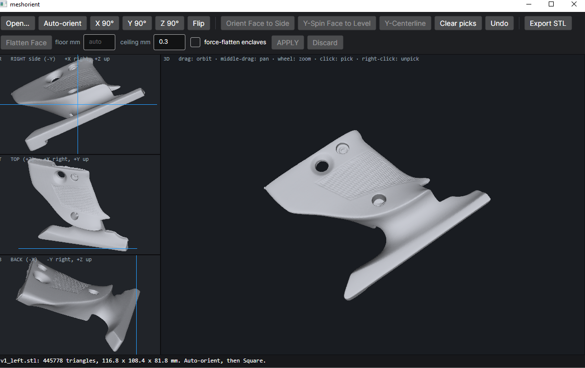
Orienting
Next, find a big flat face you think should rightly be considered on the "side" of the object. Click a bunch of points on it to place red dots. Using more points helps to reduce the impact of scan noise and will average out closer to the "real" surface plane, so I usually click about 7 or 8 spots and try to spread them out over the face.
If you misplace a dot, right-clicking will remove it.
Use the "Orient Face to Side" button to spin the model around, making that face parallel to the XZ plane.
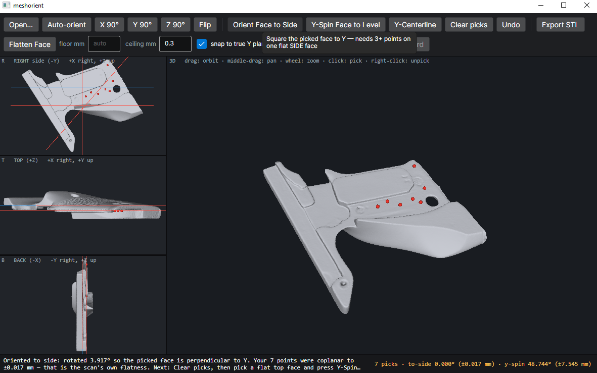
At this point the model is still slightly woppyjaw, as the "R: Right Side" panel shows. To resolve this, we want to spin it around the Y-axis only, not altering our previously selected XZ-plane parallelism.
Spinning
Hit "Clear picks" to remove your existing red dots. Now make a new selection on a plane that you feel represents the "top" or "bottom" of your model. Again, try to spread out your dots so the tool can average these points out to ignore noise.
Use the "Y-Spin Face to Level" button to spin the model so this plane is on top/bottom. This only rotates around the Y-axis, so it doesn't mess up the alignment you accomplished with "Orient Face to Side".
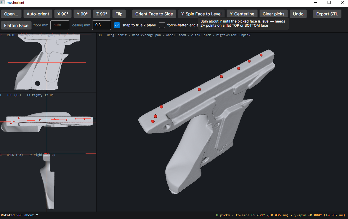
If it comes through "upside down" from what you intended, just use the "Y 90" button a couple times to flip it over.
Centerline
The example file I'm using in these screenshots isn't really a use case for this, but sometimes I get a file where I care about centering it left-to-right along the Y-axis.
To do that, clear picks again, and make new picks. This time, place picks on two different faces. These should be faces with clearly different Y-axis values!
Then click "Y-Centerline" and the model will be shifted over so that those two faces are symmetric about the centerline, i.e. one face is at Y=k and the other is at Y=-k.
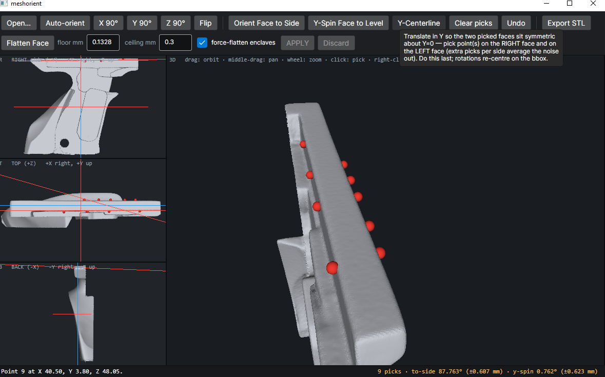
Obviously, this feature only makes sense to use after the model has been oriented using the previously mentioned tools. It will not alter the rotation, it will only slide it along the Y-axis. Think Blender "G-Y" keyboard command.
Export
The "Export STL" button will write "x_oriented.stl" where x is whatever filename you have open. Meshorient never overwrites the original opened file. It will however eagerly clobber x_oriented.stl if it already exists, so be aware of that.
Flattening
Using the same basic approach of placing red dots, you can identify any approximately-flat plane on the model and use "Flatten Face" to smush it down to true flat.
The green preview shows the area that will be affected, and the "APPLY" button makes it take effect.
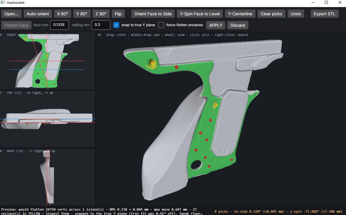
Note that flattening is special. It actually edits the model, it doesn't just rotate and translate it. For this reason,
if you've applied any "flatten" operations, "Export STL" will generate two files. It will export both
"x_oriented.stl" and "x_cleaned.stl". The _cleaned file has all your edits, including flattening. The _oriented
version only has the rotations and translations, so you can keep the original scan in full fidelity, just more
conveniently rotated.
Understanding the Flattening Tool
This tool "flood fills" outward from your selected dots to find the affected verts. Unlike the select->coplanar tool in Blender, it doesn't jump across gaps and pull in faces from unconnected areas of the model.
Applying purely moves the vertices to snap them to the inferred average plane of your selection. It doesn't simplify the topology and the triangle count doesn't change. You'll need to use Blender's decimate or another tool for that if that's what you want. For my purposes (printing and CAD/CAM) I usually do not need to worry about simplifying polycount.
Floor and Ceiling
The "ceiling mm" parameter is the max distance from the intended plane a vert can be before it's considered no longer in plane. Think of this as the tolerance of the flood fill.
The "floor mm" parameter is a little more complex. Any vert that is below floor mm will get fully, 100% snapped to the intended plane when you apply the flattening. But verts that are between floor and ceiling will get an attenuated snap.
This is important when you have a flat plane that runs into a gentle curved slope. It preserves some smoothness to the transition, whereas if you use the same value for floor and ceiling, there'll be a jagged, raised edge created where the snap-to-plane pulled up (or down) some of the verts from the start of the slope, then suddenly stopped.
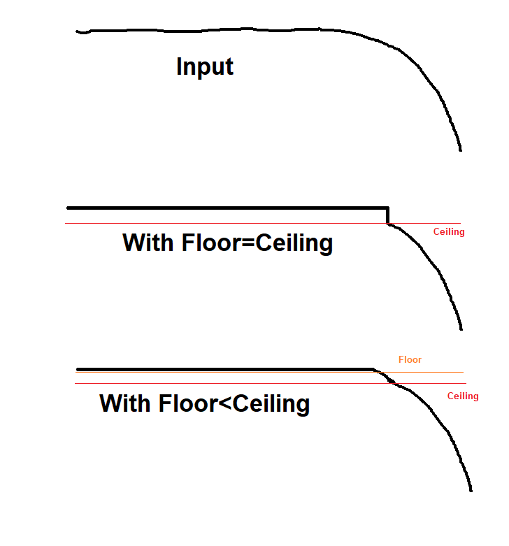
"floor mm" gets auto-populated for your selection based on the deviation of your red dot pick points from their fitted plane. This is a guesstimate for the size of ordinary scan noise found within a flat plane.
Enclaves
The green highlight shows the faces that will be affected. Yellow highlights are "enclaves", parts of the topology that are fully surrounded by flood-filled areas, but are too far out-of-plane (in excess of ceiling mm) to be included.
If you check the box "force-flatten enclaves" it'll bring those in too, utterly ignoring the fact that they are NOT really coplanar and may be hugely deviant from the plane. It will force them to get a full-value plane snap not even attenuated by floor-ceiling distance. Attenuation in this case would only leave lumpy defects behind in the middle of flat surfaces. This option is occasionally useful for deleting an undesired feature that left a lump/bump in the scan data on a plane.
Once "force-flatten enclaves" is checked you'll note the yellow area expands. This indicates the areas that will get the full-snap treatment, which includes a band around the original enclave zones so that there are no dimple or lump "rings" left behind.
Snap to true plane
If the plane formed to fit the chosen points is within 2 degrees of the true X, Y, or Z normal, you will also have the option to "snap to true [X,Y,Z] plane". This is likely to happen if you followed the orientation steps before doing any flattening.
This makes the flatten tool create a surface normal to the aforementioned world axis. In most cases this is desirable, so it's checked by default. Having a large flat surface on the model be almost-but-not-quite-exactly parallel to a world plane can be frustrating if you're later trying to use it as a reference for CAD or do CSG with other models, and this feature allows you to avoid that pain.
Similar repos


Languages
F#
100.0%
Simple slopcoded tool I use to orient/center STL data from 3d scans
F#
0
38 commits
updated Oct 2, 2026
See what people are saying
README
meshorient
Small tool I shamelessly slopcoded for processing 3D scans before I work on them in Blender or other programs.
Unlike the robo-extruded code, this README is 100% human written.
This is my workflow for getting a scan STL rotated to axis alignment and slightly cleaned up. Nothing here is particularly novel, but I find this tool fast and convenient. It does the specific things I needed. It is my default file association for .stl files since it's also a serviceable viewer app.
Features
- Align selected face to the XZ plane
- Spin to align another selected face to the X-axis
- Center the model between two chosen opposite faces
- Flatten near-flat faces, removing scan noise and optionally snapping to true world-plane alignment
Usage
First, open an STL, OBJ, or PLY file. If it's fresh off a 3D scan it will probably come in with some arbitrary, unaligned orientation.
Orienting
Next, find a big flat face you think should rightly be considered on the "side" of the object. Click a bunch of points on it to place red dots. Using more points helps to reduce the impact of scan noise and will average out closer to the "real" surface plane, so I usually click about 7 or 8 spots and try to spread them out over the face.
If you misplace a dot, right-clicking will remove it.
Use the "Orient Face to Side" button to spin the model around, making that face parallel to the XZ plane.
At this point the model is still slightly woppyjaw, as the "R: Right Side" panel shows. To resolve this, we want to spin it around the Y-axis only, not altering our previously selected XZ-plane parallelism.
Spinning
Hit "Clear picks" to remove your existing red dots. Now make a new selection on a plane that you feel represents the "top" or "bottom" of your model. Again, try to spread out your dots so the tool can average these points out to ignore noise.
Use the "Y-Spin Face to Level" button to spin the model so this plane is on top/bottom. This only rotates around the Y-axis, so it doesn't mess up the alignment you accomplished with "Orient Face to Side".
If it comes through "upside down" from what you intended, just use the "Y 90" button a couple times to flip it over.
Centerline
The example file I'm using in these screenshots isn't really a use case for this, but sometimes I get a file where I care about centering it left-to-right along the Y-axis.
To do that, clear picks again, and make new picks. This time, place picks on two different faces. These should be faces with clearly different Y-axis values!
Then click "Y-Centerline" and the model will be shifted over so that those two faces are symmetric about the centerline, i.e. one face is at Y=k and the other is at Y=-k.
Obviously, this feature only makes sense to use after the model has been oriented using the previously mentioned tools. It will not alter the rotation, it will only slide it along the Y-axis. Think Blender "G-Y" keyboard command.
Export
The "Export STL" button will write "x_oriented.stl" where x is whatever filename you have open. Meshorient never overwrites the original opened file. It will however eagerly clobber x_oriented.stl if it already exists, so be aware of that.
Flattening
Using the same basic approach of placing red dots, you can identify any approximately-flat plane on the model and use "Flatten Face" to smush it down to true flat.
The green preview shows the area that will be affected, and the "APPLY" button makes it take effect.
Note that flattening is special. It actually edits the model, it doesn't just rotate and translate it. For this reason,
if you've applied any "flatten" operations, "Export STL" will generate two files. It will export both
"x_oriented.stl" and "x_cleaned.stl". The _cleaned file has all your edits, including flattening. The _oriented
version only has the rotations and translations, so you can keep the original scan in full fidelity, just more
conveniently rotated.
Understanding the Flattening Tool
This tool "flood fills" outward from your selected dots to find the affected verts. Unlike the select->coplanar tool in Blender, it doesn't jump across gaps and pull in faces from unconnected areas of the model.
Applying purely moves the vertices to snap them to the inferred average plane of your selection. It doesn't simplify the topology and the triangle count doesn't change. You'll need to use Blender's decimate or another tool for that if that's what you want. For my purposes (printing and CAD/CAM) I usually do not need to worry about simplifying polycount.
Floor and Ceiling
The "ceiling mm" parameter is the max distance from the intended plane a vert can be before it's considered no longer in plane. Think of this as the tolerance of the flood fill.
The "floor mm" parameter is a little more complex. Any vert that is below floor mm will get fully, 100% snapped to the intended plane when you apply the flattening. But verts that are between floor and ceiling will get an attenuated snap.
This is important when you have a flat plane that runs into a gentle curved slope. It preserves some smoothness to the transition, whereas if you use the same value for floor and ceiling, there'll be a jagged, raised edge created where the snap-to-plane pulled up (or down) some of the verts from the start of the slope, then suddenly stopped.
"floor mm" gets auto-populated for your selection based on the deviation of your red dot pick points from their fitted plane. This is a guesstimate for the size of ordinary scan noise found within a flat plane.
Enclaves
The green highlight shows the faces that will be affected. Yellow highlights are "enclaves", parts of the topology that are fully surrounded by flood-filled areas, but are too far out-of-plane (in excess of ceiling mm) to be included.
If you check the box "force-flatten enclaves" it'll bring those in too, utterly ignoring the fact that they are NOT really coplanar and may be hugely deviant from the plane. It will force them to get a full-value plane snap not even attenuated by floor-ceiling distance. Attenuation in this case would only leave lumpy defects behind in the middle of flat surfaces. This option is occasionally useful for deleting an undesired feature that left a lump/bump in the scan data on a plane.
Once "force-flatten enclaves" is checked you'll note the yellow area expands. This indicates the areas that will get the full-snap treatment, which includes a band around the original enclave zones so that there are no dimple or lump "rings" left behind.
Snap to true plane
If the plane formed to fit the chosen points is within 2 degrees of the true X, Y, or Z normal, you will also have the option to "snap to true [X,Y,Z] plane". This is likely to happen if you followed the orientation steps before doing any flattening.
This makes the flatten tool create a surface normal to the aforementioned world axis. In most cases this is desirable, so it's checked by default. Having a large flat surface on the model be almost-but-not-quite-exactly parallel to a world plane can be frustrating if you're later trying to use it as a reference for CAD or do CSG with other models, and this feature allows you to avoid that pain.
Similar repos
Languages
F#
100.0%