Learn how to connect your Flexispot (LoctekMotion) desk to the internet. This repository contains a collection of scripts to get your started, combined with research and instructions.
C++
1,024
242 commits
updated Oct 13, 2026
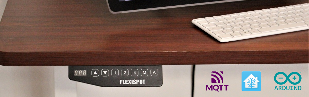 (image source: Windows Central)
[!WARNING] Be careful. Tinkering with electronics can be risky. Use this guide at your own risk.
When I assembled my FlexiSpot standing desk, I noticed the control panel had an RJ45 cable and a second RJ45 port. This sparked my interest: can I connect my desk to the internet?
Most Flexispot models utilize components from LoctekMotion, a manufacturer specializing in lifting columns for height-adjustable desks. Although LoctekMotion previously advertised a Bluetooth receiver for their control boxes, I haven't been able to obtain one.
This repository will guide you on connecting your desk to Home Assistant and other systems using the serial communication ports (RJ45). Imagine controlling your desk with your voice or receiving notifications when you've been sitting too long. Or, just do it because it's cool 🤓.
| Name | Description |
|---|---|
| ESPHome | Control your desk via an ESP32 module connected to Home Assistant. Can be adapted to ESP8266 or other ESP32 variant. |
| ESPHome Pass-through | Control desks which have only one RJ45 port using passthrough configuration via an ESP32 module connected to Home Assistant. |
For v1 packages (Arduino, Raspberry Pi, older ESPHome packages, and different pin-outs), visit the archive directory. For alternative solutions, see similar projects.
Please follow the ESPHome documentation for the basics of ESPHome. You can use the provided office-desk-esp32.yaml as a boilerplate for your own implementation. This implementation has been created for the ESP32 nodemcu, but can easily be adopted for other platforms and boards.
| RJ45 pin (T-568B) | Name | ESP32 |
|---|---|---|
| 8 🟫 | +5V (VDD) | VIN |
| 7 ⬜🟫 | GND | GND |
| 6 🟩 | TX | TX2 (GPIO17) |
| 5 ⬜🟦 | RX | RX2 (GPIO16) |
| 4 🟦 | PIN 20 | D23 (GPIO23) |
| 3 ⬜🟩 | (unknown) | |
| 2 🟧 | SWIM | |
| 1 ⬜🟧 | RES |
You can use other GPIO pins (e.g. on an ESP32-C3) by changing the tx_pin, rx_pin and screen_pin substitutions in the package.
This pin-out should be compatible with all control panels featuring an RJ45 port for serial communication. If it doesn't work for your setup, consider trying an alternative pin-out from the archive.
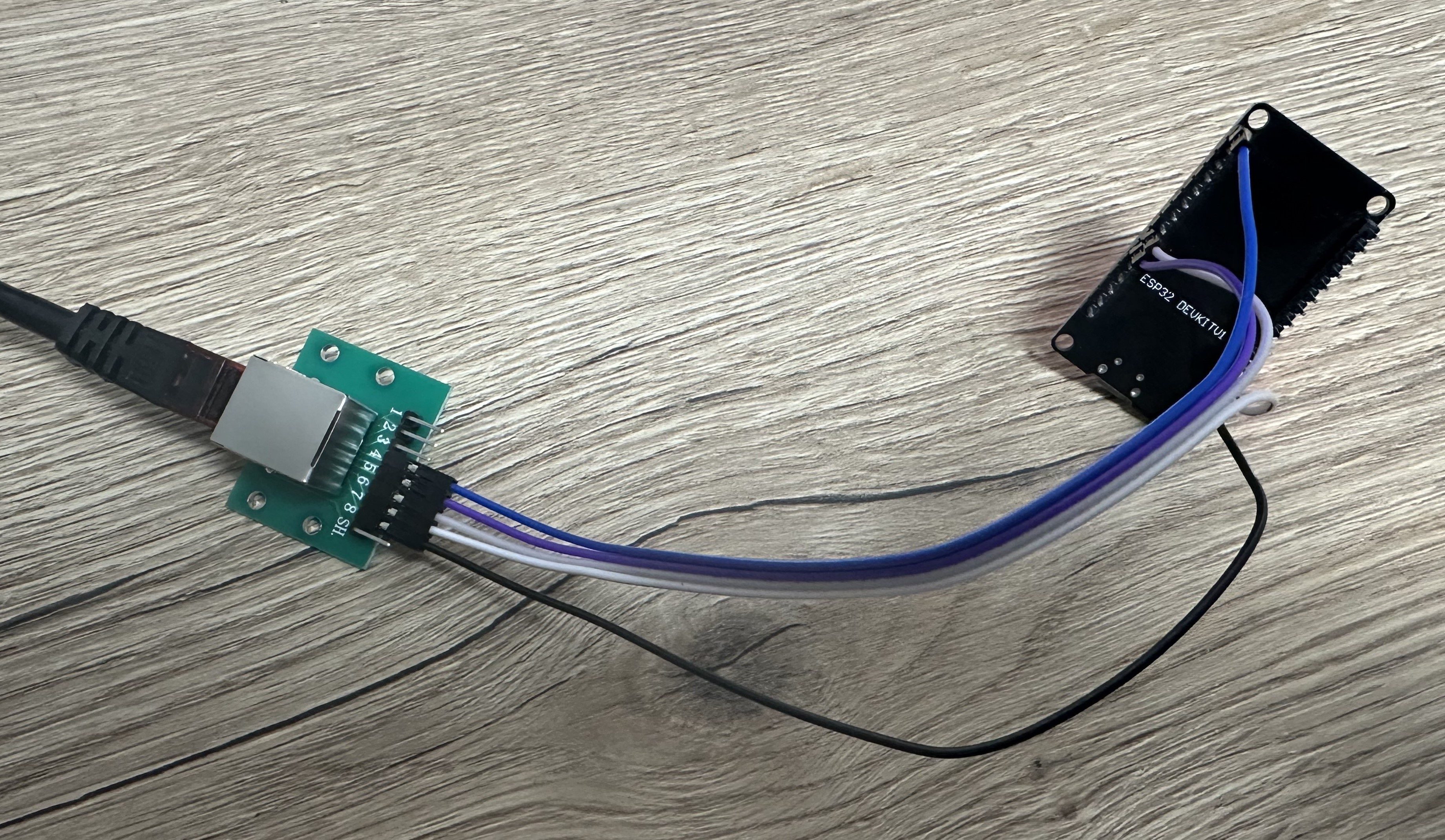
Use the provided pin-out to connect your ESP32 to the desk controller's RJ45 port using an ethernet cable. If you're not experienced with electronics and soldering, consider using an RJ45 Adapter Board from sites like Aliexpress, connected with Dupont cables to your ESP32.
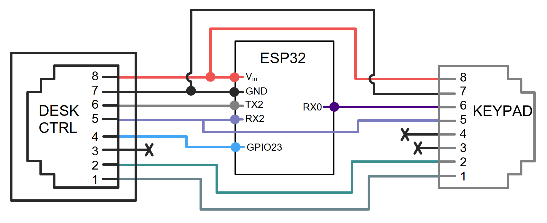
If your desk controller lacks an extra RJ45 port, you'll need a pass-through solution. This requires connecting the RJ45 of the keypad to the pins below.
| KeyPad RJ45 pin | Name | Connection |
|---|---|---|
| 8 | +5V (VDD) | VIN (Split) |
| 7 | GND | GND (Split) |
| 6 | TX | RX0 (GPIO3) |
| 5 | RX | RX2 (Split) |
| 4 | PIN 20 | (Not Required) |
| 3 | (unknown) | (Not Required) |
| 2 | SWIM | (Pass-Through) |
| 1 | RES | (Pass-Through) |
The pins marked 'split' are to be connected to the ESP32 pin, the desk controller and to the keypad. The pins marked pass-through are to be connected directly between the controller and the keypad.
Note: the current implementation does not utilize PIN20 however, this could be utilized to sense if the screen is on if desired.
To keep your setup clean and well-protected, a custom enclosure for the ESP32 DevKit with Ethernet breakout is available. It ensures secure housing, optimal cable management, and a stable wired connection.
Features ✅:
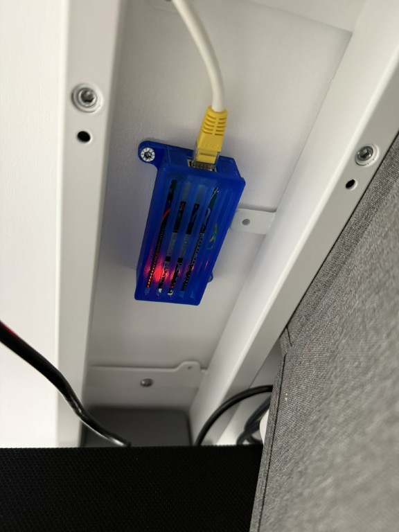
🔗 Download the enclosure model at makerworld.com.
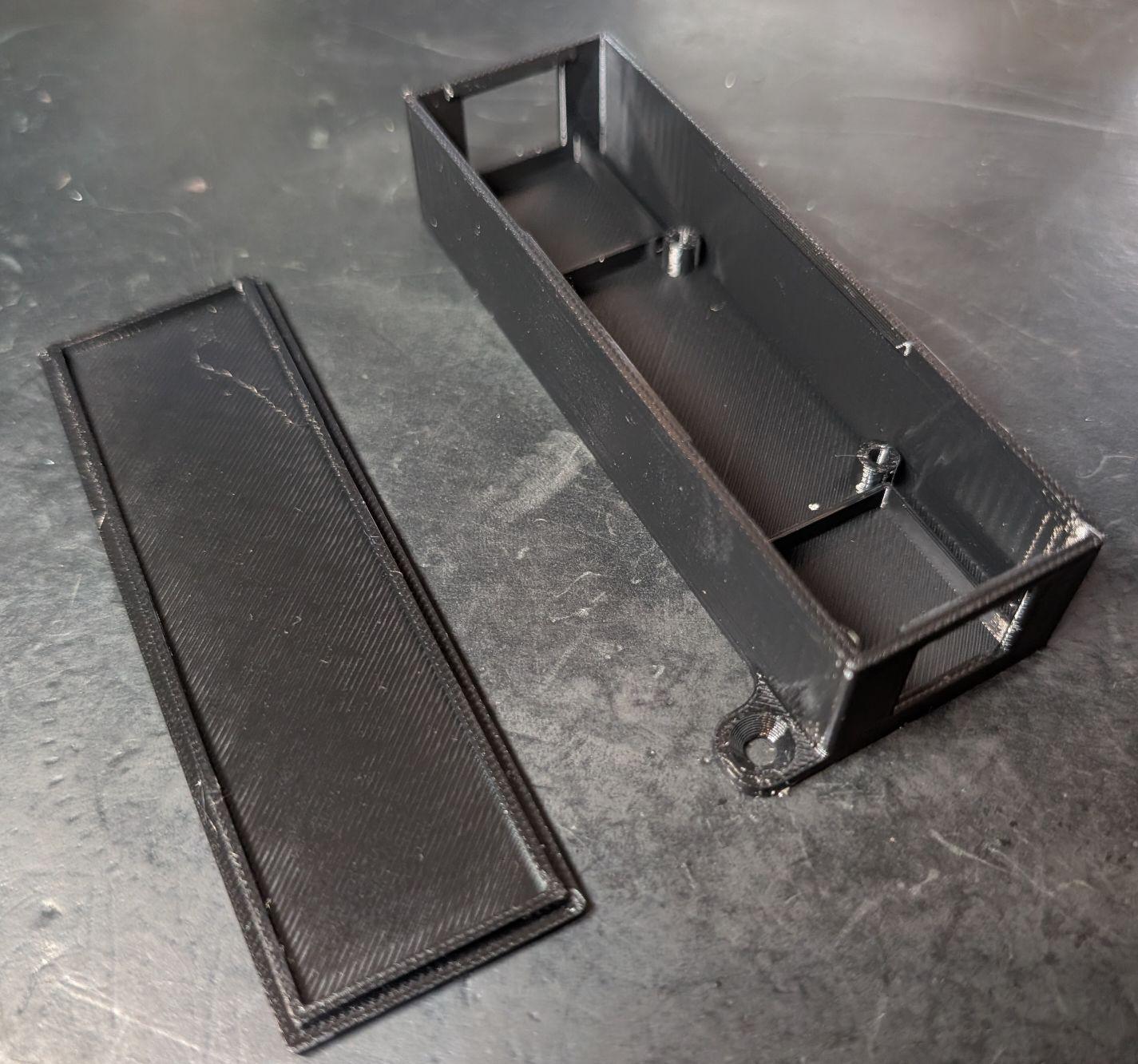
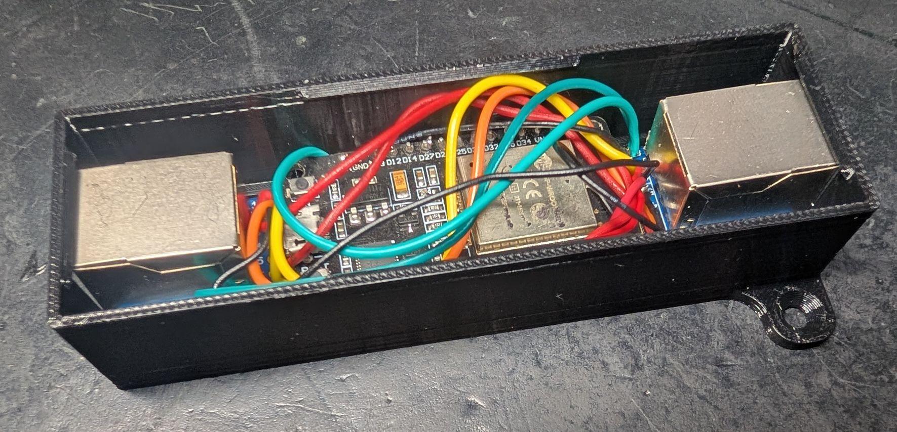
A pass-through configuration needs two RJ45 jacks, which the enclosure above does not have. This case fits an ESP32 DevKit between two RJ45 breakout boards — desk controller on one side, keypad on the other.
| Enclosure | Assembled |
|---|---|
 |  |
🔗 Models (STL + Fusion 360 source): models/passthrough-case
My height sensor is not providing the correct value
true to falsein the YAML configuration.If you are interested in the internals of the LoctecMotion desk system, have a look at the research below which is composed of my own findings combined with findings of similar projects.
At the time of writing, LoctekMotion sells 11 different control panels. The features can differ per model, but it looks like the serial interface is pretty similar for the more advanced models.
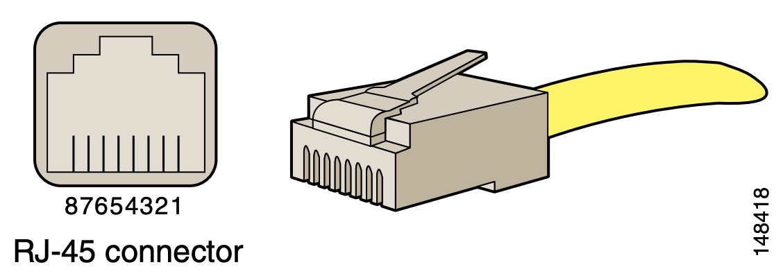
The tables below will show a mapping of the RJ45 pinout to the pinout used by the control panel. Please note that all RJ45 pins are described in the following way:
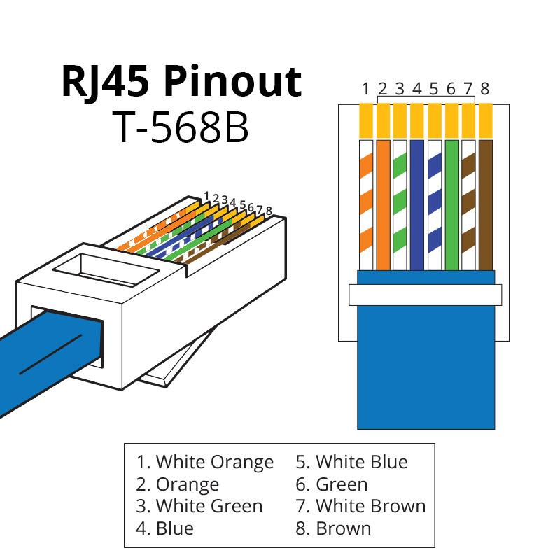
The most common color convention for wiring RJ45 for network cables is:
In order to connect the control box to a Raspberry Pi and ESP32/ESP8266 chip I used a RJ45 to RS232 adapter with DuPont cables (jump wires), but you simply can cut and split an ethernet cable as well.
[!NOTE] Eventually, we discovered that a single pin-out should work for all control panels. It seems multiple mappings can be used, but the most common one is the one used for the HS13B-1 control panel.
| RJ45 pin | Name | Original Cable Color | Ethernet cable color (T568B) |
|---|---|---|---|
| 1 | RESET | Brown | White-Orange |
| 2 | SWIM | White | Orange |
| 3 | EMPTY | Purple | White-Green |
| 4 | PIN 20 | Red | Blue |
| 5 | RX | Green | White-Blue |
| 6 | TX | Black | Green |
| 7 | GND | Blue | White-Brown |
| 8 | +5V (VDD) | Yellow | Brown |
Note that RX and TX is defined like this on receiver (control panel) side. So the custom controller also uses RX to receive data and TX to send data.
| RJ45 pin | Name | Original Cable Color | Ethernet cable color (T568B) |
|---|---|---|---|
| 1 | RESET SWIM | Brown | White-Orange |
| 2 | PIN 20 | White | Orange |
| 3 | RX | Purple | White-Green |
| 4 | TX | Red | Blue |
| 5 | GND1 | Green | White-Blue |
| 6 | +5V (VDD) | Black | Green |
| 7 | 29V+ | Blue | White-Brown |
| 8 | 29V- | Yellow | Brown |
Note that RX and TX is defined like this on receiver (control panel) side. So the custom controller also uses RX to receive data and TX to send data.
| RJ45 pin | Name |
|---|---|
| 8 | +5V (VDD) |
| 7 | GND |
| 6 | TX |
| 5 | RX |
| 4 | PIN 20 |
| 3 | (unknown) |
| 2 | SWIM |
| 1 | RES |
Note that RX and TX is defined like this on receiver (control panel) side. So the custom controller also uses RX to receive data and TX to send data.
Other control panels / control boxes could be supported in the same way, but you would need to figure the RJ45 pinout mapping. Most control boxes have an extra RJ45 port for serial communication, but otherwise you would need to place your device in between the control panel and the control box.
Based upon the great work of minifloat, it became clear that the control panel utilises a 7-segment display. Fortunately, this is very common in such devices and thus there is a lot of documentation on this topic.
The control box sends the height as 4-bit hexadecimal, which is decoded in the control panel to drive the 7-segment display. The second number on the display also supports an optional decimal point ("8 segment").
Make sure you set the baud rate to 9600. For most LoctekMotion desks, the control box only broadcasts the current height for x seconds after you sent the Wake Up command. Otherwise you will receive 0x00 0x00 0x00 as payload.
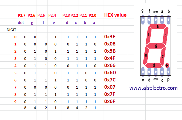
source: alselectro
The control box only accepts commands when the 'screen is active'. To activate the screen, PIN 20 needs to be set to HIGH for about 1 second. The screen gets disabled automatically again after some amount of time receiving no commands.
| Command name | Start | Length | Type | Payload | Checksum | End |
|---|---|---|---|---|---|---|
| Wake Up | 9b | 06 | 02 | 00 00 | 6c a1 | 9d |
| Up | 9b | 06 | 02 | 01 00 | fc a0 | 9d |
| Down | 9b | 06 | 02 | 02 00 | 0c a0 | 9d |
| M | 9b | 06 | 02 | 20 00 | ac b8 | 9d |
| Preset 1 | 9b | 06 | 02 | 04 00 | ac a3 | 9d |
| Preset 2 | 9b | 06 | 02 | 08 00 | ac a6 | 9d |
| Preset 3 (stand) | 9b | 06 | 02 | 10 00 | ac ac | 9d |
| Preset 4 (sit) | 9b | 06 | 02 | 00 01 | ac 60 | 9d |
All bytes combined will become the command to send to the control box. See the packages for sample code.
While working on this project, I found that many others have done similar work. Several GitHub repositories with great research have been very helpful in starting this project. ❤️
Special thanks to the Tweakers.net community (Dutch) for helping kickstart this project.
We welcome contributions from the community! If you have ideas, suggestions, or improvements, please feel free to open an issue or submit a pull request.
Join our Discord channel for a chat with like-minded people or to get help with your project.
227 followers · starred Aug 2026
706 followers · starred Oct 2024
284 followers · starred Jun 2026
64 followers · starred Jan 2022
Learn how to connect your Flexispot (LoctekMotion) desk to the internet. This repository contains a collection of scripts to get your started, combined with research and instructions.
C++
1,024
242 commits
updated Oct 13, 2026
(image source: Windows Central)
[!WARNING] Be careful. Tinkering with electronics can be risky. Use this guide at your own risk.
When I assembled my FlexiSpot standing desk, I noticed the control panel had an RJ45 cable and a second RJ45 port. This sparked my interest: can I connect my desk to the internet?
Most Flexispot models utilize components from LoctekMotion, a manufacturer specializing in lifting columns for height-adjustable desks. Although LoctekMotion previously advertised a Bluetooth receiver for their control boxes, I haven't been able to obtain one.
This repository will guide you on connecting your desk to Home Assistant and other systems using the serial communication ports (RJ45). Imagine controlling your desk with your voice or receiving notifications when you've been sitting too long. Or, just do it because it's cool 🤓.
| Name | Description |
|---|---|
| ESPHome | Control your desk via an ESP32 module connected to Home Assistant. Can be adapted to ESP8266 or other ESP32 variant. |
| ESPHome Pass-through | Control desks which have only one RJ45 port using passthrough configuration via an ESP32 module connected to Home Assistant. |
For v1 packages (Arduino, Raspberry Pi, older ESPHome packages, and different pin-outs), visit the archive directory. For alternative solutions, see similar projects.
Please follow the ESPHome documentation for the basics of ESPHome. You can use the provided office-desk-esp32.yaml as a boilerplate for your own implementation. This implementation has been created for the ESP32 nodemcu, but can easily be adopted for other platforms and boards.
| RJ45 pin (T-568B) | Name | ESP32 |
|---|---|---|
| 8 🟫 | +5V (VDD) | VIN |
| 7 ⬜🟫 | GND | GND |
| 6 🟩 | TX | TX2 (GPIO17) |
| 5 ⬜🟦 | RX | RX2 (GPIO16) |
| 4 🟦 | PIN 20 | D23 (GPIO23) |
| 3 ⬜🟩 | (unknown) | |
| 2 🟧 | SWIM | |
| 1 ⬜🟧 | RES |
You can use other GPIO pins (e.g. on an ESP32-C3) by changing the tx_pin, rx_pin and screen_pin substitutions in the package.
This pin-out should be compatible with all control panels featuring an RJ45 port for serial communication. If it doesn't work for your setup, consider trying an alternative pin-out from the archive.
Use the provided pin-out to connect your ESP32 to the desk controller's RJ45 port using an ethernet cable. If you're not experienced with electronics and soldering, consider using an RJ45 Adapter Board from sites like Aliexpress, connected with Dupont cables to your ESP32.
If your desk controller lacks an extra RJ45 port, you'll need a pass-through solution. This requires connecting the RJ45 of the keypad to the pins below.
| KeyPad RJ45 pin | Name | Connection |
|---|---|---|
| 8 | +5V (VDD) | VIN (Split) |
| 7 | GND | GND (Split) |
| 6 | TX | RX0 (GPIO3) |
| 5 | RX | RX2 (Split) |
| 4 | PIN 20 | (Not Required) |
| 3 | (unknown) | (Not Required) |
| 2 | SWIM | (Pass-Through) |
| 1 | RES | (Pass-Through) |
The pins marked 'split' are to be connected to the ESP32 pin, the desk controller and to the keypad. The pins marked pass-through are to be connected directly between the controller and the keypad.
Note: the current implementation does not utilize PIN20 however, this could be utilized to sense if the screen is on if desired.
To keep your setup clean and well-protected, a custom enclosure for the ESP32 DevKit with Ethernet breakout is available. It ensures secure housing, optimal cable management, and a stable wired connection.
Features ✅:
🔗 Download the enclosure model at makerworld.com.
A pass-through configuration needs two RJ45 jacks, which the enclosure above does not have. This case fits an ESP32 DevKit between two RJ45 breakout boards — desk controller on one side, keypad on the other.
| Enclosure | Assembled |
|---|---|
| |
🔗 Models (STL + Fusion 360 source): models/passthrough-case
My height sensor is not providing the correct value
true to falsein the YAML configuration.If you are interested in the internals of the LoctecMotion desk system, have a look at the research below which is composed of my own findings combined with findings of similar projects.
At the time of writing, LoctekMotion sells 11 different control panels. The features can differ per model, but it looks like the serial interface is pretty similar for the more advanced models.
The tables below will show a mapping of the RJ45 pinout to the pinout used by the control panel. Please note that all RJ45 pins are described in the following way:
The most common color convention for wiring RJ45 for network cables is:
In order to connect the control box to a Raspberry Pi and ESP32/ESP8266 chip I used a RJ45 to RS232 adapter with DuPont cables (jump wires), but you simply can cut and split an ethernet cable as well.
[!NOTE] Eventually, we discovered that a single pin-out should work for all control panels. It seems multiple mappings can be used, but the most common one is the one used for the HS13B-1 control panel.
| RJ45 pin | Name | Original Cable Color | Ethernet cable color (T568B) |
|---|---|---|---|
| 1 | RESET | Brown | White-Orange |
| 2 | SWIM | White | Orange |
| 3 | EMPTY | Purple | White-Green |
| 4 | PIN 20 | Red | Blue |
| 5 | RX | Green | White-Blue |
| 6 | TX | Black | Green |
| 7 | GND | Blue | White-Brown |
| 8 | +5V (VDD) | Yellow | Brown |
Note that RX and TX is defined like this on receiver (control panel) side. So the custom controller also uses RX to receive data and TX to send data.
| RJ45 pin | Name | Original Cable Color | Ethernet cable color (T568B) |
|---|---|---|---|
| 1 | RESET SWIM | Brown | White-Orange |
| 2 | PIN 20 | White | Orange |
| 3 | RX | Purple | White-Green |
| 4 | TX | Red | Blue |
| 5 | GND1 | Green | White-Blue |
| 6 | +5V (VDD) | Black | Green |
| 7 | 29V+ | Blue | White-Brown |
| 8 | 29V- | Yellow | Brown |
Note that RX and TX is defined like this on receiver (control panel) side. So the custom controller also uses RX to receive data and TX to send data.
| RJ45 pin | Name |
|---|---|
| 8 | +5V (VDD) |
| 7 | GND |
| 6 | TX |
| 5 | RX |
| 4 | PIN 20 |
| 3 | (unknown) |
| 2 | SWIM |
| 1 | RES |
Note that RX and TX is defined like this on receiver (control panel) side. So the custom controller also uses RX to receive data and TX to send data.
Other control panels / control boxes could be supported in the same way, but you would need to figure the RJ45 pinout mapping. Most control boxes have an extra RJ45 port for serial communication, but otherwise you would need to place your device in between the control panel and the control box.
Based upon the great work of minifloat, it became clear that the control panel utilises a 7-segment display. Fortunately, this is very common in such devices and thus there is a lot of documentation on this topic.
The control box sends the height as 4-bit hexadecimal, which is decoded in the control panel to drive the 7-segment display. The second number on the display also supports an optional decimal point ("8 segment").
Make sure you set the baud rate to 9600. For most LoctekMotion desks, the control box only broadcasts the current height for x seconds after you sent the Wake Up command. Otherwise you will receive 0x00 0x00 0x00 as payload.
source: alselectro
The control box only accepts commands when the 'screen is active'. To activate the screen, PIN 20 needs to be set to HIGH for about 1 second. The screen gets disabled automatically again after some amount of time receiving no commands.
| Command name | Start | Length | Type | Payload | Checksum | End |
|---|---|---|---|---|---|---|
| Wake Up | 9b | 06 | 02 | 00 00 | 6c a1 | 9d |
| Up | 9b | 06 | 02 | 01 00 | fc a0 | 9d |
| Down | 9b | 06 | 02 | 02 00 | 0c a0 | 9d |
| M | 9b | 06 | 02 | 20 00 | ac b8 | 9d |
| Preset 1 | 9b | 06 | 02 | 04 00 | ac a3 | 9d |
| Preset 2 | 9b | 06 | 02 | 08 00 | ac a6 | 9d |
| Preset 3 (stand) | 9b | 06 | 02 | 10 00 | ac ac | 9d |
| Preset 4 (sit) | 9b | 06 | 02 | 00 01 | ac 60 | 9d |
All bytes combined will become the command to send to the control box. See the packages for sample code.
While working on this project, I found that many others have done similar work. Several GitHub repositories with great research have been very helpful in starting this project. ❤️
Special thanks to the Tweakers.net community (Dutch) for helping kickstart this project.
We welcome contributions from the community! If you have ideas, suggestions, or improvements, please feel free to open an issue or submit a pull request.
Join our Discord channel for a chat with like-minded people or to get help with your project.
227 followers · starred Aug 2026
706 followers · starred Oct 2024
284 followers · starred Jun 2026
64 followers · starred Jan 2022