This repository contains the PSLab-Mini hardware design files. PSLab-Mini is a scaled-down version of the PSLab board, aiming to provide instruments for doing signal measurements. It consists of an Oscilloscope, a Logic analyzer, and a Multimeter.
It also integrates an ESP chip in conjunction with the main MCU(STM32), for enabling wireless connectivity via the board.
| Front Side | Back Side |
|---|---|
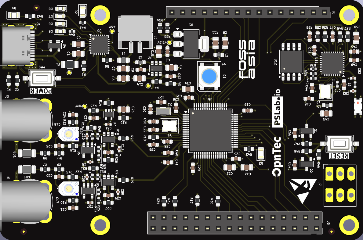 | 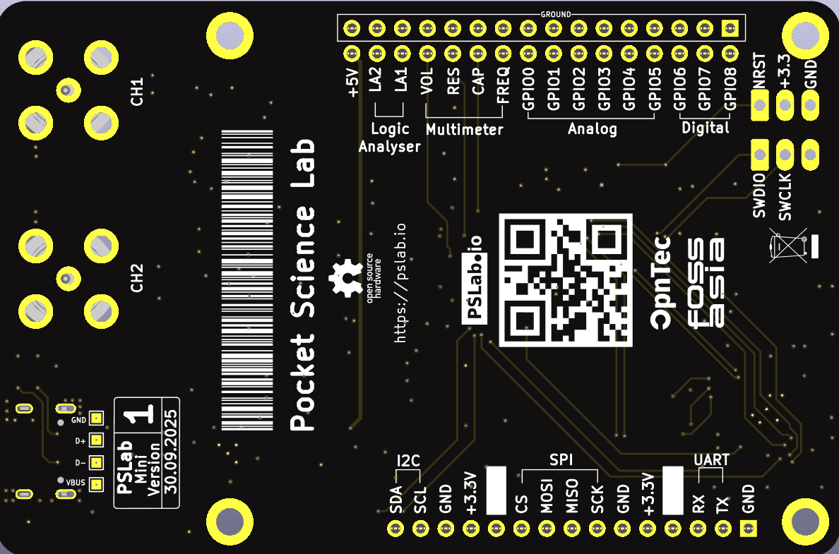 |
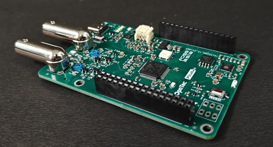 | 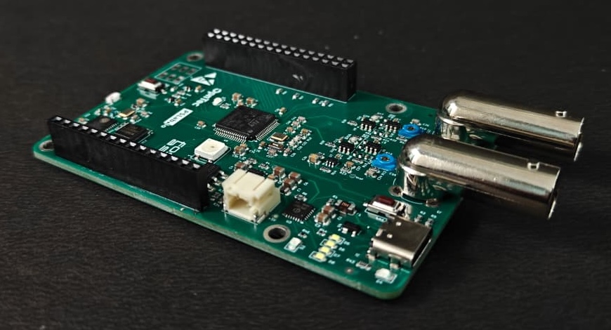 |
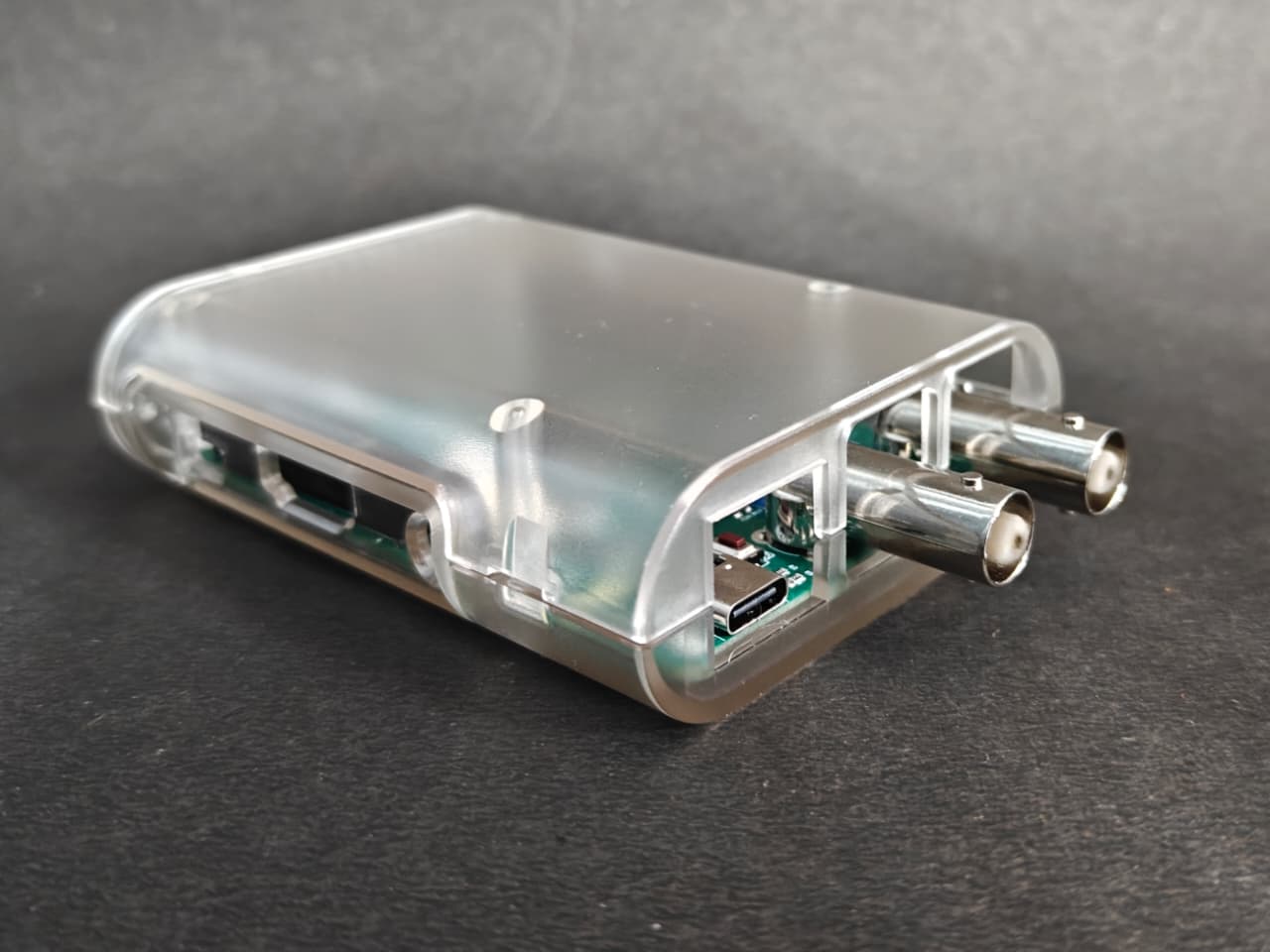
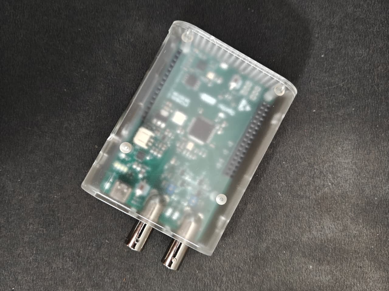
The PSLab Mini is designed to use Raspberry Pi 3/4 Cases, which are already widely available, without any modification.
All the ports remain accessible in the casing (USB, BNC Connectors, and battery connector).
 |  |
Oscilloscope
Logic Analyser
Multimeter
| Pin Name | Pin (on Microcontroller) | Type |
|---|---|---|
| GPIO 0 | PA5 | Analog Pin |
| GPIO 1 | PA6 | Analog Pin |
| GPIO 2 | PA7 | Analog Pin |
| GPIO 3 | PC4 | Analog Pin |
| GPIO 4 | PC5 | Analog Pin |
| GPIO 5 | PB0 | Analog Pin |
| GPIO 6 | PC8 | Digital Pin |
| GPIO 7 | PC9 | Digital Pin |
| GPIO 8 | PA8 | Digital Pin |
| Pin Name | Pin (on Microcontroller) | Type |
|---|---|---|
| LA1 | PA3 | Logic Analyser Channel-1 |
| LA2 | PA2 | Logic Analyser Channel-2 |
| FQY | PA4 | Frequency Measurement |
| VOL | PC0 | Voltage Measurement |
| RES | PC1 | Resistance Measurement |
| CAP | PC3 | Capacitance Measurement |
| Connector Number | Pin (on Microcontroller) | Type |
|---|---|---|
| CH1 | PA0 | Oscilloscope Channel-1 |
| CH2 | PA1 | Oscilloscope Channel-2 |
| UART_1 | Connected to ESP32 |
| SPI_2 | Connected to ESP32 |
| UART_6 | Connected to External header pins |
| SPI_3 | Connected to External header pins |
| I2C_1 | Connected to External header pins |
| SPI_1 | Connected to External NOR flash |
| UART_1 | Connected to STM32 |
| SPI_2 | Connected to STM32 |
The reset button on the board resets both the STM32 and the ESP32 simultaneously.
In addition, the STM32 can reset ESP32 through an output pin:
PB5 (STM32) → CHIP_EN (ESP32)
62 followers · starred Sep 2019
107 followers · starred Sep 2018
This repository contains the PSLab-Mini hardware design files. PSLab-Mini is a scaled-down version of the PSLab board, aiming to provide instruments for doing signal measurements. It consists of an Oscilloscope, a Logic analyzer, and a Multimeter.
It also integrates an ESP chip in conjunction with the main MCU(STM32), for enabling wireless connectivity via the board.
| Front Side | Back Side |
|---|---|
| |
| |
The PSLab Mini is designed to use Raspberry Pi 3/4 Cases, which are already widely available, without any modification.
All the ports remain accessible in the casing (USB, BNC Connectors, and battery connector).
| |
Oscilloscope
Logic Analyser
Multimeter
| Pin Name | Pin (on Microcontroller) | Type |
|---|---|---|
| GPIO 0 | PA5 | Analog Pin |
| GPIO 1 | PA6 | Analog Pin |
| GPIO 2 | PA7 | Analog Pin |
| GPIO 3 | PC4 | Analog Pin |
| GPIO 4 | PC5 | Analog Pin |
| GPIO 5 | PB0 | Analog Pin |
| GPIO 6 | PC8 | Digital Pin |
| GPIO 7 | PC9 | Digital Pin |
| GPIO 8 | PA8 | Digital Pin |
| Pin Name | Pin (on Microcontroller) | Type |
|---|---|---|
| LA1 | PA3 | Logic Analyser Channel-1 |
| LA2 | PA2 | Logic Analyser Channel-2 |
| FQY | PA4 | Frequency Measurement |
| VOL | PC0 | Voltage Measurement |
| RES | PC1 | Resistance Measurement |
| CAP | PC3 | Capacitance Measurement |
| Connector Number | Pin (on Microcontroller) | Type |
|---|---|---|
| CH1 | PA0 | Oscilloscope Channel-1 |
| CH2 | PA1 | Oscilloscope Channel-2 |
| UART_1 | Connected to ESP32 |
| SPI_2 | Connected to ESP32 |
| UART_6 | Connected to External header pins |
| SPI_3 | Connected to External header pins |
| I2C_1 | Connected to External header pins |
| SPI_1 | Connected to External NOR flash |
| UART_1 | Connected to STM32 |
| SPI_2 | Connected to STM32 |
The reset button on the board resets both the STM32 and the ESP32 simultaneously.
In addition, the STM32 can reset ESP32 through an output pin:
PB5 (STM32) → CHIP_EN (ESP32)
62 followers · starred Sep 2019
107 followers · starred Sep 2018