A fully featured audio DSP firmware for the Raspberry Pi Pico (RP2040) and Pico 2 (RP2350). Official Discord: https://discord.gg/RCyqxAQ5xS
C
1,355
347 commits
updated Oct 12, 2026
DSPi transforms a Raspberry Pi Pico or other RP2040-based board into a very competent and inexpensive little digital audio processor. It acts as a USB sound card with an onboard DSP engine, allowing you to make use of essential tools like room correction, active crossovers, parametric EQ, time alignment, loudness compensation, and headphone crossfeed.
It is my hope that the RP2040 and RP2350 will garner a reputation as the "swiss army knife of audio for less than a cup of coffee".
Feel free to join the official Discord server for development updates, discussion or to request assistance!
| Feature | RP2040 (Pico) | RP2350 (Pico 2) |
|---|---|---|
| System Clock | 307.2 MHz (overclock) | 307.2 MHz |
| Core Voltage | 1.15 V | 1.15 V |
| Sample Rates | 44.1 / 48 / 96 kHz | 44.1 / 48 / 96 kHz |
| Audio Processing | Q28 Fixed-Point | Single-Precision Float |
| EQ Bands | 10 per channel (70 total) | 10 per channel (110 total) |
| Total Channels | 7 (2 master + 4 S/PDIF·I2S + 1 PDM) | 11 (2 master + 8 S/PDIF·I2S + 1 PDM) |
| Output Slots | 2 stereo (each S/PDIF or I2S) | 4 stereo (each S/PDIF or I2S) |
| Output Bit Depth | 24-bit | 24-bit |
| PDM Output | 1 (subwoofer) | 1 (subwoofer) |
| Max Delay | 85ms per output | 85ms per output |
| Math Engine | Hand-optimized ARM Assembly | Hardware FPU (hybrid SVF/biquad EQ) |
| Dual-Core EQ | Yes (Core 1 processes outputs 3-4) | Yes (Core 1 processes outputs 3-8) |
| User Presets | 10 slots | 10 slots |
| S/PDIF Input | Yes | Yes |
| Status | Production | Production |
Both platforms are fully tested and production-ready. The RP2040 reaches 307.2 MHz with a slight voltage bump; the RP2350 hits the same frequency at the same voltage. Clock is fixed (no rate-dependent switching), and PIO dividers are integer at every supported sample rate. The RP2350 offers significantly more processing headroom thanks to its hardware floating-point unit, enabling more output channels and a hybrid SVF/biquad filter architecture for improved low-frequency accuracy.
DSPi processes audio in a linear, low-latency pipeline:
RP2350 (11 channels, 9 outputs):
USB Input (16/24-bit PCM Stereo, 44.1 / 48 / 96 kHz)
or
S/PDIF Input (24 bit PCM Stereo, 44.1 / 48 kHz)
    |
PASS 1: Per-Channel Preamp (independent L/R gain) + USB Volume
    |
PASS 2: Master EQ (10 bands per channel, Left/Right)
    |
PASS 2.5: Volume Leveller (RMS upward compression, optional)
    |
PASS 3: Headphone Crossfeed (BS2B + ITD, optional) + Master Peak Metering
    |
        Loudness Compensation (volume-dependent EQ, optional)
    |
PASS 4: Matrix Mixer (2 inputs x 9 outputs, per-crosspoint gain & phase)
    |
PASS 5: Per-Output EQ -> Gain/Mute -> Delay -> Output Gain × Master Volume
    |
    +-- Out 1-2 --> S/PDIF or I2S slot 0 (data: GPIO 6 default)
    +-- Out 3-4 --> S/PDIF or I2S slot 1 (data: GPIO 7 default)
    +-- Out 5-6 --> S/PDIF or I2S slot 2 (data: GPIO 8 default)
    +-- Out 7-8 --> S/PDIF or I2S slot 3 (data: GPIO 9 default)
    +-- Out 9   --> PDM Sub               (data: GPIO 10 default)
                  (I2S BCK/LRCLK shared on GPIO 14/15 default; optional MCK on GPIO 13 default)
RP2040 (7 channels, 5 outputs):
USB Input (16/24-bit PCM Stereo, 44.1 / 48 / 96 kHz)
or
S/PDIF Input (24 bit PCM Stereo, 44.1 / 48 kHz)
    |
PASS 1: Per-Channel Preamp + USB Volume
    |
PASS 2: Master EQ (10 bands per channel, Left/Right)
    |
PASS 2.5: Volume Leveller (RMS upward compression, optional)
    |
PASS 3: Headphone Crossfeed (BS2B + ITD, optional) + Master Peak Metering
    |
        Loudness Compensation (volume-dependent EQ, optional)
    |
PASS 4: Matrix Mixer (2 inputs x 5 outputs, per-crosspoint gain & phase)
    |
PASS 5: Per-Output EQ -> Gain/Mute -> Delay -> Output Gain × Master Volume
    |
    +-- Out 1-2 --> S/PDIF or I2S slot 0 (data: GPIO 6 default)
    +-- Out 3-4 --> S/PDIF or I2S slot 1 (data: GPIO 7 default)
    +-- Out 5   --> PDM Sub               (data: GPIO 10 default)
                  (I2S BCK/LRCLK shared on GPIO 14/15 default; optional MCK on GPIO 13 default)
DSPi.uf2 release for your board.RPI-RP2 will appear..uf2 file onto this drive.RP2350 (Pico 2) — up to 8 output pins:
| Function | Pin | Connection |
|---|---|---|
| S/PDIF Input | GPIO 5 (default) | S/PDIF Input |
| Output Slot 0 (Out 1-2) | GPIO 6 (default) | S/PDIF or I2S data for main L/R or multi-way pair 1 |
| Output Slot 1 (Out 3-4) | GPIO 7 (default) | S/PDIF or I2S data for multi-way pair 2 |
| Output Slot 2 (Out 5-6) | GPIO 8 (default) | S/PDIF or I2S data for multi-way pair 3 |
| Output Slot 3 (Out 7-8) | GPIO 9 (default) | S/PDIF or I2S data for multi-way pair 4 |
| Subwoofer Out (PDM, Out 9) | GPIO 10 (default) | Active subwoofer or PDM-to-analog filter |
| I2S BCK (shared, I2S only) | GPIO 14 (default) | Bit clock for any slot configured as I2S |
| I2S LRCLK (I2S only) | GPIO 15 (BCK + 1, fixed) | Word/frame clock; always BCK + 1 |
| I2S MCK (optional) | GPIO 13 (default) | 128× or 256× Fs master clock when MCK is enabled |
| USB | Micro-USB | Host device (PC/Mac/Mobile Device) |
RP2040 (Pico) — up to 6 output pins:
| Function | Pin | Connection |
|---|---|---|
| S/PDIF Input | GPIO 5 (default) | S/PDIF Input |
| Output Slot 0 (Out 1-2) | GPIO 6 (default) | S/PDIF or I2S data for main L/R or stereo pair 1 |
| Output Slot 1 (Out 3-4) | GPIO 7 (default) | S/PDIF or I2S data for stereo pair 2 |
| Subwoofer Out (PDM, Out 5) | GPIO 10 (default) | Active subwoofer or PDM-to-analog filter |
| I2S BCK (shared, I2S only) | GPIO 14 (default) | Bit clock for any slot configured as I2S |
| I2S LRCLK (I2S only) | GPIO 15 (BCK + 1, fixed) | Word/frame clock; always BCK + 1 |
| I2S MCK (optional) | GPIO 13 (default) | 128× or 256× Fs master clock when MCK is enabled |
| USB | Micro-USB | Host device (PC/Mac/Mobile Device) |
Warning: RP2040 input pins are not 5v tolerant, use only 3.3v external devices such as optical receivers.
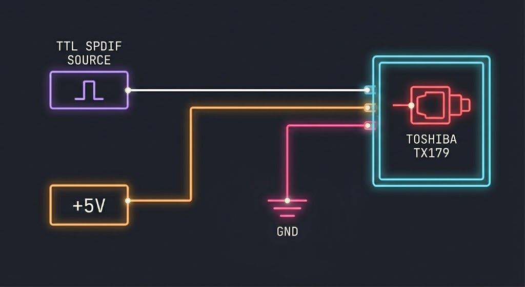
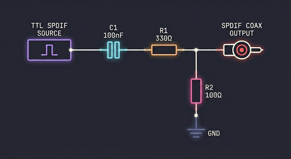
Notes: S/PDIF input requires either a Toshiba TORX141 optical receiver or a suitable receiver circuit. Possible receiver circuits are described by ST Microelectronics here. S/PDIF output requires either a Toshiba TX179 optical transmitter or a simple resistor divider. I2S output is a standard 24-bit-in-32-bit left-justified frame — wires straight into most I2S DACs. PDM output is a 1-bit logic signal that requires a resistor and capacitor to form a low-pass filter for conversion to analog audio.
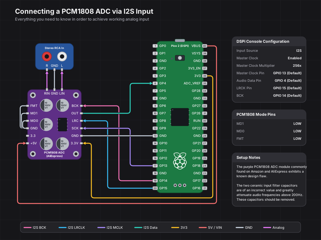
Use the PCM1808 in slave, standard-I2S mode: MD1 = LOW, MD0 = LOW, and FMT = LOW. In DSPi Console, select I2S as the input source, set RX data to GPIO 4, keep BCK on GPIO 14 (GPIO 15 is LRCLK), enable MCK on GPIO 13, and set the MCK multiplier to 256x. That gives the PCM1808 SCKI/MCLK frequencies of 11.2896 MHz at 44.1 kHz, 12.288 MHz at 48 kHz, and 24.576 MHz at 96 kHz.
PCM1808 modules vary: some expose separate VDD/3V3 and VCC/5V pins, while others have a regulator and only expose VCC. Follow the module silkscreen for power, keep all digital I/O at 3.3 V logic, and always share ground with the Pico 2.
All default pin assignments above work out of the box, but every output pin — including I2S BCK and MCK — can be reassigned at runtime through the DSPi Console application. No reflashing required. This is useful when designing custom PCBs or adapting to boards where the default GPIOs are inconvenient.
Pin assignments are saved to flash and restored automatically at boot. A few GPIOs are reserved and unavailable for output use: GPIO 12 (UART TX) and GPIOs 23-25 (power control and LED). LRCLK is always pinned to BCK + 1 due to a PIO side-set constraint.
The matrix mixer routes the USB stereo input to all output channels. RP2350 has a 2x9 matrix (9 outputs), RP2040 has a 2x5 matrix (5 outputs). Each crosspoint (input/output pair) has:
Each output channel also has:
Output Availability: Core 1 is shared between the PDM subwoofer modulator and the EQ worker that processes higher-numbered S/PDIF outputs. PDM and EQ worker modes are mutually exclusive:
RP2350:
| Mode | Available Outputs | Core 1 Usage |
|---|---|---|
| PDM enabled (Out 9 on) | Out 1-2 (S/PDIF 1) + Out 9 (PDM) | Delta-sigma modulator |
| PDM disabled (Out 9 off) | Out 1-8 (S/PDIF 1-4) | EQ worker for Out 3-8 |
RP2040:
| Mode | Available Outputs | Core 1 Usage |
|---|---|---|
| PDM enabled (Out 5 on) | Out 1-2 (S/PDIF 1) + Out 5 (PDM) | Delta-sigma modulator |
| PDM disabled (Out 5 off) | Out 1-4 (S/PDIF 1-2) | EQ worker for Out 3-4 |
When the PDM subwoofer is active, Core 1 is fully dedicated to the delta-sigma modulator, so higher-numbered S/PDIF outputs are unavailable. When PDM is off, Core 1 runs as an EQ worker processing those outputs in parallel with Core 0.
Common Configurations (RP2350):
| Use Case | Routing | Mode |
|---|---|---|
| Stereo + Sub | L→Out1, R→Out2, L+R→Out9 | PDM on (3 outputs) |
| 2-Way Active | L→Out1(tweeter), L→Out3(woofer), R→Out2(tweeter), R→Out4(woofer) | PDM off (4 outputs) |
| 3-Way Active | As above, plus mid-range on Out5-6 | PDM off (6 outputs) |
| 4-Way Active | As above, plus super-tweeter on Out7-8 | PDM off (8 outputs) |
Common Configurations (RP2040):
| Use Case | Routing | Mode |
|---|---|---|
| Stereo | L→Out1, R→Out2 | PDM off (2 outputs) |
| Stereo + Sub | L→Out1, R→Out2, L+R→Out5 | PDM on (3 outputs) |
| 2-Way Active | L→Out1(tweeter), L→Out3(woofer), R→Out2(tweeter), R→Out4(woofer) | PDM off (4 outputs) |
Each band can be set to any of these 14 types. Every type uses a corner/center frequency; Q and gain apply only where listed (other types ignore them).
| Type | Order | Parameters | Description |
|---|---|---|---|
| Flat | - | - | Bypass; the band does nothing (auto-skipped for zero CPU) |
| Peaking | 2nd | freq, Q, gain | Parametric bell; boost or cut centered on freq, width set by Q |
| Low Shelf | 2nd | freq, Q, gain | Boost/cut everything below freq; Q sets the transition slope |
| High Shelf | 2nd | freq, Q, gain | Boost/cut everything above freq; Q sets the transition slope |
| Low Pass | 2nd | freq, Q | 12 dB/oct rolloff above freq; Q sets corner resonance |
| High Pass | 2nd | freq, Q | 12 dB/oct rolloff below freq; Q sets corner resonance |
| Notch | 2nd | freq, Q | Deep, narrow null at freq; Q sets width |
| All-Pass | 2nd | freq, Q | Flat magnitude; rotates phase 0 to -360 deg (phase / group-delay tool) |
| First-Order All-Pass | 1st | freq | Flat magnitude; rotates phase 0 to -180 deg (-90 deg at freq) |
| First-Order Low Shelf | 1st | freq, gain | Gentle 6 dB/oct low shelf; monotonic, no Q or overshoot |
| First-Order High Shelf | 1st | freq, gain | Gentle 6 dB/oct high shelf; monotonic, no Q or overshoot |
| Linkwitz Transform | 2nd | freq (f0), Q (Q0), gain (fp in Hz), target Q | Replaces a driver's measured sealed-box rolloff (f0, Q0) with a target alignment (fp, Qp) for bass extension; see PEQ filters |
| First-Order Low Pass | 1st | freq | Gentle 6 dB/oct rolloff above freq; -3 dB at freq, no resonance |
| First-Order High Pass | 1st | freq | Gentle 6 dB/oct rolloff below freq; -3 dB at freq, no resonance |
Frequency ranges from 10 Hz to 0.45xFs; Q from 0.1 to 20. First-order types are single-pole (6 dB/oct) and have no resonance.
On RP2040, all filters use biquad IIR (Transposed Direct Form II) with Q28 fixed-point arithmetic. On RP2350, the firmware uses a hybrid SVF/biquad architecture: filters below Fs/7.5 (~6.4 kHz at 48 kHz) use the Cytomic SVF (linear trapezoid) topology for superior numerical accuracy at low frequencies, while higher frequencies use traditional TDF2 biquad. Flat bands (and zero-gain peaking/shelf bands) are automatically bypassed for zero CPU overhead.
Channel Layout:
RP2350 (11 channels):
| Channel | Index | EQ Bands |
|---|---|---|
| Master Left | 0 | 10 |
| Master Right | 1 | 10 |
| Output 1-8 (S/PDIF) | 2-9 | 10 each |
| Output 9 (PDM Sub) | 10 | 10 |
RP2040 (7 channels):
| Channel | Index | EQ Bands |
|---|---|---|
| Master Left | 0 | 10 |
| Master Right | 1 | 10 |
| Output 1-4 (S/PDIF) | 2-5 | 10 each |
| Output 5 (PDM Sub) | 6 | 10 |
In addition to the parametric bands above, every output channel has up to 4 dedicated crossover filter bands for building active multi-way speaker and subwoofer systems. Crossover filters are low-pass or high-pass only and are tuned by corner frequency alone (Q and gain are not used). Three families are available:
| Family | Orders | Slopes | Character |
|---|---|---|---|
| Linkwitz-Riley (LR) | 2, 4, 6, 8 | 12 / 24 / 36 / 48 dB/oct | -6 dB at the corner; an LP and HP pair at the same frequency sum to flat magnitude. LR4 (24 dB/oct) is the de-facto studio and hi-fi standard. |
| Butterworth (BW) | 1-8 | 6 / 12 / 18 / 24 / 30 / 36 / 42 / 48 dB/oct | -3 dB at the corner; maximally flat passband. BW1 is a gentle 6 dB/oct first-order slope. |
| Bessel (BES) | 2, 4, 6, 8 | 12 / 24 / 36 / 48 dB/oct | Maximally flat group delay for the best transient response and phase behavior. |
Each crossover filter is built from a cascade of up to four biquad sections. On RP2350 the same hybrid rule applies per section (sections below Fs/7.5 use the Cytomic SVF for low-frequency accuracy). Crossover bands exist on output channels only, separate from and in addition to that channel's 10 parametric bands. A typical 2-way active speaker drives one output through a high-pass crossover (tweeter/mid) and another through a low-pass (woofer); a subwoofer output usually takes a low-pass.
Based on the ISO 226:2003 equal-loudness contour standard. At low listening volumes, the human ear is less sensitive to bass and treble frequencies. Loudness compensation applies a volume-dependent EQ curve to maintain perceived tonal balance across all listening levels.
Implements Bauer Stereophonic-to-Binaural (BS2B) crossfeed with a complementary filter design that reduces unnatural stereo separation for headphone listening. Each channel receives a lowpass-filtered, time-delayed mix of the opposite channel, simulating the acoustic crossfeed that occurs with loudspeaker listening.
| Preset | Cutoff | Feed Level | Character |
|---|---|---|---|
| Default | 700 Hz | 4.5 dB | Balanced, most popular |
| Chu Moy | 700 Hz | 6.0 dB | Stronger spatial effect |
| Jan Meier | 650 Hz | 9.5 dB | Subtle, natural |
| Custom | 500-2000 Hz | 0-15 dB | User-defined |
A feedforward, stereo-linked, single-band RMS dynamic range compressor that maintains consistent perceived volume across content with varying loudness.
The leveller sits at PASS 2.5 — after Master EQ, before crossfeed. Independent of Loudness Compensation; both can be enabled together without conflict.
Each USB input channel (Left and Right) has an independent preamp gain in dB, applied at PASS 1 before any other processing. Useful for trimming channel imbalance, attenuating hot inputs ahead of EQ, or matching levels across sources. A legacy single-value command remains for backward compatibility (sets both channels to the same value).
A device-side output ceiling applied at the very end of the signal chain, independent of USB host volume.
MASTER_VOL_DEFAULT_DB in firmware).Each output slot can be switched at runtime between S/PDIF (default) and I2S, independently per slot. A single device can drive a mix — e.g., slot 0 as I2S into a DAC chip, slot 1 as S/PDIF over Toslink to an external receiver, all from the same audio pipeline.
The DSP pipeline is identical for both output types — only the final encoding differs (BMC/NRZI for S/PDIF vs. raw left-justified PCM for I2S).
The subwoofer output uses a high-performance software-defined delta-sigma modulator running on Core 1.
The objective was to use as much of Core 1 as necessary to produce an output that could be used full-range while sounding perfectly fine, even if it will only be used to feed a subwoofer. This implementation is very stable and without pops, clicks or idle tones.
DSPi includes a 10-slot preset system that stores complete DSP configurations in flash. A preset is always active — there is no "no preset" state.
Note: PDM mode and EQ Worker mode are mutually exclusive on Core 1. When the PDM output is enabled, Core 0 handles all S/PDIF output EQ processing. When PDM is disabled and higher-numbered outputs are active, Core 1 runs as an EQ worker for those outputs.
Both platforms run at a fixed 307.2 MHz system clock (VCO 1536 MHz / 5 / 1) so PIO dividers stay integer at every supported sample rate, eliminating sample-rate-dependent clock switching glitches.
| Platform | System Clock | Core Voltage |
|---|---|---|
| RP2040 | 307.2 MHz (overclock) | 1.15 V |
| RP2350 | 307.2 MHz | 1.15 V |
The RP2040 reaches 307.2 MHz with a slight voltage bump above the 1.10 V nominal; the RP2350 is comfortable at the same voltage at this clock. The voltage step is applied before the frequency change. Sample rate changes do not retune the system clock, only the PIO dividers, so transitions between 44.1 / 48 / 96 kHz are seamless.
Flash access is also tuned: PICO_FLASH_SPI_CLKDIV is set to 6 to keep XIP and erase/program operations safely below the W25Q080's 104–133 MHz spec at this clock. On the RP2350, runtime QMI register management is handled by firmware/DSPi/flash_clkdiv.c since the bootrom does not honor the boot2 setting on that platform.
Configuration is performed via Interface 2 (Vendor Interface) using Control Transfers under Windows and via Interface 0 under macOS. The device supports WinUSB/WCID for automatic driverless installation on Windows.
Request Table
| Code | Name | Direction | Payload | Description |
|---|---|---|---|---|
0x42 | REQ_SET_EQ_PARAM | OUT | 16 bytes | Upload filter parameters |
0x43 | REQ_GET_EQ_PARAM | IN | 16 bytes | Read filter parameters |
0x44 | REQ_SET_PREAMP | OUT | 4 bytes | Set global gain (float dB) |
0x45 | REQ_GET_PREAMP | IN | 4 bytes | Get global gain |
0x46 | REQ_SET_BYPASS | OUT | 1 byte | Bypass Master EQ (1=On, 0=Off) |
0x47 | REQ_GET_BYPASS | IN | 1 byte | Get bypass state |
0x48 | REQ_SET_DELAY | OUT | 4 bytes | Set channel delay (float ms) |
0x49 | REQ_GET_DELAY | IN | 4 bytes | Get channel delay |
0x50 | REQ_GET_STATUS | IN | 4-12 bytes | Get system statistics (wValue selects field) |
0x51 | REQ_SAVE_PARAMS | IN | 1 byte | Save to active preset slot |
0x52 | REQ_LOAD_PARAMS | IN | 1 byte | Reload active preset slot |
0x53 | REQ_FACTORY_RESET | IN | 1 byte | Reset live state to defaults |
0x54 | REQ_SET_CHANNEL_GAIN | OUT | 4 bytes | Set output channel gain (float dB) |
0x55 | REQ_GET_CHANNEL_GAIN | IN | 4 bytes | Get output channel gain |
0x56 | REQ_SET_CHANNEL_MUTE | OUT | 1 byte | Mute output channel (1=Muted) |
0x57 | REQ_GET_CHANNEL_MUTE | IN | 1 byte | Get mute state |
0x58 | REQ_SET_LOUDNESS | OUT | 1 byte | Enable/disable loudness (1=On) |
0x59 | REQ_GET_LOUDNESS | IN | 1 byte | Get loudness state |
0x5A | REQ_SET_LOUDNESS_REF | OUT | 4 bytes | Set reference SPL (float, 40-100) |
0x5B | REQ_GET_LOUDNESS_REF | IN | 4 bytes | Get reference SPL |
0x5C | REQ_SET_LOUDNESS_INTENSITY | OUT | 4 bytes | Set intensity % (float, 0-200) |
0x5D | REQ_GET_LOUDNESS_INTENSITY | IN | 4 bytes | Get intensity |
0x5E | REQ_SET_CROSSFEED | OUT | 1 byte | Enable/disable crossfeed (1=On) |
0x5F | REQ_GET_CROSSFEED | IN | 1 byte | Get crossfeed state |
0x60 | REQ_SET_CROSSFEED_PRESET | OUT | 1 byte | Set preset (0-3) |
0x61 | REQ_GET_CROSSFEED_PRESET | IN | 1 byte | Get current preset |
0x62 | REQ_SET_CROSSFEED_FREQ | OUT | 4 bytes | Set custom frequency (float Hz, 500-2000) |
0x63 | REQ_GET_CROSSFEED_FREQ | IN | 4 bytes | Get custom frequency |
0x64 | REQ_SET_CROSSFEED_FEED | OUT | 4 bytes | Set custom feed level (float dB, 0-15) |
0x65 | REQ_GET_CROSSFEED_FEED | IN | 4 bytes | Get custom feed level |
0x66 | REQ_SET_CROSSFEED_ITD | OUT | 1 byte | Enable/disable ITD (1=On) |
0x67 | REQ_GET_CROSSFEED_ITD | IN | 1 byte | Get ITD state |
0x70 | REQ_SET_MATRIX_ROUTE | OUT | 8 bytes | Set matrix crosspoint (MatrixRoutePacket) |
0x71 | REQ_GET_MATRIX_ROUTE | IN | 8 bytes | Get matrix crosspoint |
0x72 | REQ_SET_OUTPUT_ENABLE | OUT | 1 byte | Enable/disable output channel |
0x73 | REQ_GET_OUTPUT_ENABLE | IN | 1 byte | Get output enable state |
0x74 | REQ_SET_OUTPUT_GAIN | OUT | 4 bytes | Set per-output gain (float dB) |
0x75 | REQ_GET_OUTPUT_GAIN | IN | 4 bytes | Get per-output gain |
0x76 | REQ_SET_OUTPUT_MUTE | OUT | 1 byte | Mute output (1=Muted) |
0x77 | REQ_GET_OUTPUT_MUTE | IN | 1 byte | Get output mute state |
0x78 | REQ_SET_OUTPUT_DELAY | OUT | 4 bytes | Set per-output delay (float ms) |
0x79 | REQ_GET_OUTPUT_DELAY | IN | 4 bytes | Get per-output delay |
0x7A | REQ_GET_CORE1_MODE | IN | 1 byte | Get Core 1 mode (0=Idle, 1=PDM, 2=EQ Worker) |
0x7B | REQ_GET_CORE1_CONFLICT | IN | 1 byte | Check if PDM vs EQ Worker conflict exists |
0x7C | REQ_SET_OUTPUT_PIN | IN | 1 byte | Change output GPIO pin (returns status) |
0x7D | REQ_GET_OUTPUT_PIN | IN | 1 byte | Get current GPIO pin for an output |
0x7E | REQ_GET_SERIAL | IN | variable | Get unique board serial number |
0x7F | REQ_GET_PLATFORM | IN | 1 byte | Get platform ID (0=RP2040, 1=RP2350) |
0x83 | REQ_CLEAR_CLIPS | OUT | — | Clear clip detection latches |
0x90 | REQ_PRESET_SAVE | IN | 1 byte | Save live state to preset slot (wValue=slot) |
0x91 | REQ_PRESET_LOAD | IN | 1 byte | Load preset slot to live state (wValue=slot) |
0x92 | REQ_PRESET_DELETE | IN | 1 byte | Delete preset slot (wValue=slot) |
0x93 | REQ_PRESET_GET_NAME | IN | 32 bytes | Get preset name (wValue=slot) |
0x94 | REQ_PRESET_SET_NAME | OUT | 32 bytes | Set preset name (wValue=slot) |
0x95 | REQ_PRESET_GET_DIR | IN | variable | Get preset directory (occupancy, startup config) |
0x96 | REQ_PRESET_SET_STARTUP | OUT | 2 bytes | Set startup mode and default slot |
0x97 | REQ_PRESET_GET_STARTUP | IN | 2 bytes | Get startup configuration |
0x98 | REQ_PRESET_SET_INCLUDE_PINS | OUT | 1 byte | Set pin config inclusion (1=include) |
0x99 | REQ_PRESET_GET_INCLUDE_PINS | IN | 1 byte | Get pin config inclusion setting |
0x9A | REQ_PRESET_GET_ACTIVE | IN | 1 byte | Get currently active preset slot index |
0x9B | REQ_SET_CHANNEL_NAME | OUT | 32 bytes | Set channel name (wValue=channel) |
0x9C | REQ_GET_CHANNEL_NAME | IN | 32 bytes | Get channel name (wValue=channel) |
0xA0 | REQ_GET_ALL_PARAMS | IN | ~2896 bytes | Bulk read entire DSP state (multi-packet) |
0xA1 | REQ_SET_ALL_PARAMS | OUT | ~2896 bytes | Bulk write entire DSP state (multi-packet) |
0xB0 | REQ_GET_BUFFER_STATS | IN | variable | Read buffer fill statistics |
0xB1 | REQ_RESET_BUFFER_STATS | IN | 1 byte | Reset buffer statistics counters |
0xB2 | REQ_GET_USB_ERROR_STATS | IN | 24 bytes | Read USB PHY error counters (CRC/bit-stuff/timeout/overflow/seq) |
0xB3 | REQ_RESET_USB_ERROR_STATS | IN | 1 byte | Reset USB PHY error counters |
0xB4 | REQ_SET_LEVELLER_ENABLE | OUT | 1 byte | Enable/disable Volume Leveller |
0xB5 | REQ_GET_LEVELLER_ENABLE | IN | 1 byte | Get leveller enable state |
0xB6 | REQ_SET_LEVELLER_AMOUNT | OUT | 4 bytes | Set leveller target/amount (float) |
0xB7 | REQ_GET_LEVELLER_AMOUNT | IN | 4 bytes | Get leveller amount |
0xB8 | REQ_SET_LEVELLER_SPEED | OUT | 1 byte | Set leveller attack/release speed |
0xB9 | REQ_GET_LEVELLER_SPEED | IN | 1 byte | Get leveller speed |
0xBA | REQ_SET_LEVELLER_MAX_GAIN | OUT | 4 bytes | Set max upward gain (float dB) |
0xBB | REQ_GET_LEVELLER_MAX_GAIN | IN | 4 bytes | Get max upward gain |
0xBC | REQ_SET_LEVELLER_LOOKAHEAD | OUT | 1 byte | Enable/disable 10 ms lookahead |
0xBD | REQ_GET_LEVELLER_LOOKAHEAD | IN | 1 byte | Get lookahead state |
0xBE | REQ_SET_LEVELLER_GATE | OUT | 4 bytes | Set noise-gate threshold (float dB) |
0xBF | REQ_GET_LEVELLER_GATE | IN | 4 bytes | Get noise-gate threshold |
0xC0 | REQ_SET_OUTPUT_TYPE | OUT | 1 byte | Set slot output type (0=S/PDIF, 1=I2S; wValue=slot) |
0xC1 | REQ_GET_OUTPUT_TYPE | IN | 1 byte | Get slot output type (wValue=slot) |
0xC2 | REQ_SET_I2S_BCK_PIN | OUT | 1 byte | Set shared I2S BCK GPIO (LRCLK auto = BCK + 1) |
0xC3 | REQ_GET_I2S_BCK_PIN | IN | 1 byte | Get current I2S BCK pin |
0xC4 | REQ_SET_MCK_ENABLE | OUT | 1 byte | Enable/disable I2S master clock output |
0xC5 | REQ_GET_MCK_ENABLE | IN | 1 byte | Get MCK enable state |
0xC6 | REQ_SET_MCK_PIN | OUT | 1 byte | Set MCK GPIO |
0xC7 | REQ_GET_MCK_PIN | IN | 1 byte | Get MCK GPIO |
0xC8 | REQ_SET_MCK_MULTIPLIER | OUT | 1 byte | Set MCK multiplier (0=128×, 1=256×) |
0xC9 | REQ_GET_MCK_MULTIPLIER | IN | 1 byte | Get MCK multiplier |
0xD0 | REQ_SET_PREAMP_CH | OUT | 4 bytes | Set per-channel preamp (wValue=channel, payload=float dB) |
0xD1 | REQ_GET_PREAMP_CH | IN | 4 bytes | Get per-channel preamp (wValue=channel) |
0xD2 | REQ_SET_MASTER_VOLUME | OUT | 4 bytes | Set master volume (-128 mute sentinel, -127..0 dB) |
0xD3 | REQ_GET_MASTER_VOLUME | IN | 4 bytes | Get current live master volume |
0xD4 | REQ_SET_MASTER_VOLUME_MODE | OUT | 1 byte | Set persistence mode (0=independent, 1=with preset) |
0xD5 | REQ_GET_MASTER_VOLUME_MODE | IN | 1 byte | Get persistence mode |
0xD6 | REQ_SAVE_MASTER_VOLUME | IN | 1 byte | Save live master volume to directory (mode 0 persistence) |
0xD7 | REQ_GET_SAVED_MASTER_VOLUME | IN | 4 bytes | Read directory's saved master-volume value |
0xF0 | REQ_ENTER_BOOTLOADER | IN | 1 byte | Reboot into UF2 bootloader for firmware update |
The REQ_GET_STATUS request returns data based on the wValue field:
| wValue | Returns | Description |
|---|---|---|
0 | uint32 | Peaks for channels 0-1 (packed 16-bit values) |
1 | uint32 | Peaks for channels 2-3 (packed 16-bit values) |
2 | uint32 | Peak for channel 4 + CPU0/CPU1 load (packed) |
3 | uint32 | PDM ring buffer overruns |
4 | uint32 | PDM ring buffer underruns |
5 | uint32 | PDM DMA overruns |
6 | uint32 | PDM DMA underruns |
7 | uint32 | S/PDIF overruns |
8 | uint32 | S/PDIF underruns |
9 | 12 bytes | Combined: all 5 peaks + CPU loads |
10 | uint32 | USB audio packet count |
11 | uint32 | USB alt setting |
12 | uint32 | USB audio mounted state |
13 | uint32 | System clock frequency (Hz) |
14 | uint32 | Core voltage (millivolts) |
15 | uint32 | Sample rate (Hz) |
16 | int32 | System temperature (centi-degrees C) |
17 | uint32 | Total S/PDIF DMA starvations (all slots combined) |
18 | uint32 | S/PDIF slot 0 starvations (Out 1-2) |
19 | uint32 | S/PDIF slot 1 starvations (Out 3-4) |
20 | uint32 | S/PDIF slot 2 starvations (Out 5-6, RP2350) |
21 | uint32 | S/PDIF slot 3 starvations (Out 7-8, RP2350) |
A starvation event means the S/PDIF DMA needed a buffer but the consumer pool was empty, so the firmware substituted a silence buffer for that transfer. This is a more direct output-side dropout signal than the older spdif_underruns USB-packet-gap heuristic.
Filter Packet (16 bytes):
struct __attribute__((packed)) {
    uint8_t channel;  // RP2350: 0-10, RP2040: 0-6
    uint8_t band;     // 0-9
    uint8_t type;     // 0=Flat, 1=Peak, 2=LS, 3=HS, 4=LP, 5=HP
    uint8_t reserved;
    float freq;       // Hz
    float Q;
    float gain_db;
}
Matrix Route Packet (8 bytes):
struct __attribute__((packed)) {
    uint8_t input;          // 0-1 (USB L/R)
    uint8_t output;         // RP2350: 0-8, RP2040: 0-4
    uint8_t enabled;        // 0 or 1
    uint8_t phase_invert;   // 0 or 1
    float gain_db;          // -inf to +12dB
}
Output GPIO pins can be reassigned at runtime without reflashing. This is useful for custom PCB layouts or when the default pin assignments conflict with other hardware.
REQ_SET_OUTPUT_PIN (0x7C) — IN transfer, returns 1-byte status:
wValue = (new_pin << 8) | output_indexoutput_index 0-3 for S/PDIF outputs 1-4, 4 for PDM subwooferoutput_index 0-1 for S/PDIF outputs 1-2, 2 for PDM subwooferREQ_SET_OUTPUT_ENABLE), otherwise returns PIN_CONFIG_OUTPUT_ACTIVE| Status Code | Value | Meaning |
|---|---|---|
PIN_CONFIG_SUCCESS | 0x00 | Pin changed successfully |
PIN_CONFIG_INVALID_PIN | 0x01 | Pin out of range or reserved (GPIO 12, 23-25) |
PIN_CONFIG_PIN_IN_USE | 0x02 | Pin already assigned to another output |
PIN_CONFIG_INVALID_OUTPUT | 0x03 | Output index out of range |
PIN_CONFIG_OUTPUT_ACTIVE | 0x04 | PDM output must be disabled before changing its pin |
REQ_GET_OUTPUT_PIN (0x7D) — IN transfer, returns 1 byte:
wValue = output_indexPin assignments are stored in each preset and can optionally be included during preset save/load (controlled via REQ_PRESET_SET_INCLUDE_PINS).
A build-flag-gated capture path for bench measurement and automated verification. When the firmware is compiled with DSPI_LOOPBACK, the device exposes a second USB Audio Class 1 function that streams output slot 0 back to the host as a recording input, so a host tool can play a signal into DSPi and record exactly what slot 0 produced. This folds the capability of the standalone Weeb Labs USBrx (an external S/PDIF-to-USB recorder) into DSPi itself, removing the second board and the S/PDIF jumper from the loopback rig. The feature is excluded from release builds; a production device never exposes the capture endpoint.
Building
The loopback build lives in dedicated build directories so release artifacts are unaffected:
# Configure once (from the repo root):
cmake -S firmware -B build-rp2040-loopback -DPICO_PLATFORM=rp2040       -DPICO_BOARD=pico  -DDSPI_LOOPBACK=ON
cmake -S firmware -B build-rp2350-loopback -DPICO_PLATFORM=rp2350-arm-s -DPICO_BOARD=pico2 -DDSPI_LOOPBACK=ON

# Build, then flash build-<plat>-loopback/DSPi/DSPi.uf2:
cmake --build build-rp2040-loopback -j
cmake --build build-rp2350-loopback -j
DSPI_LOOPBACK is a CMake option (default OFF); enabling it adds loopback.c to the target and defines the DSPI_LOOPBACK macro that gates every firmware change. With the flag off, the build is byte-for-byte identical to the normal firmware.
USB topology
The capture is a self-contained UAC1 audio function appended after the vendor interface, so the existing interfaces (0 Audio Control, 1 Audio Streaming, 2 Vendor) keep their numbers. The configuration descriptor grows from 207 to 309 bytes.
| Element | Value |
|---|---|
| Interface 3 | Capture Audio Control (own IAD grouping interfaces 3 + 4) |
| Interface 4 | Capture Audio Streaming (alt 0 zero-bandwidth, alt 1 streaming) |
| Endpoint | 0x81 isochronous, asynchronous IN, bInterval 1 |
wMaxPacketSize | 384 bytes (64 stereo frames of headroom) |
| Format | Type I PCM, 2 channels, 24-bit, 44.1 / 48 kHz |
| Terminals | Input terminal ID 4 (internal: slot 0) feeds Output terminal ID 5 (USB streaming) |
The host sees one USB device with both a playback output and a 2-channel capture input. On macOS these appear as two Core Audio entries that share the name "Weeb Labs DSPi" (one with output channels, one with input channels). The Microsoft OS 2.0 / WinUSB descriptors are unchanged: their Function Subset still scopes WinUSB to the vendor interface only, so adding the capture function does not disturb driverless vendor-interface binding on Windows.
Capture data path
output slot 0 (audio_pipeline.c, post-DSP, pre-encode)
  -> loopback_push_slot0() -> SPSC ring (1024 frames, ~8 KB, .bss)
      -> rate-matching servo (fill_audio_packet, per USB frame)
          -> iso async IN endpoint 0x81 -> USB host
process_input_block() reads slot 0's finished, interleaved 24-bit samples from audio_buf[0] immediately before the buffer is handed to the output DMA. It runs after all DSP (EQ, crossover, matrix, gain, delay, mute) and before the output encoder, so it captures exactly what slot 0 sends out whether slot 0 is configured as S/PDIF or I2S. The tap is read-only: it copies samples out and never writes back, so it cannot perturb the firmware's inter-slot output alignment.int32 per frame, ~8 KB in .bss). The producer is the audio pipeline; the consumer is the USB transfer-complete callback. Both run in core-0 thread context, so plain volatile head/tail indices are sufficient. On overflow (host not draining) the producer drops frames and the servo re-primes.Rate-matching servo
The capture IN endpoint is asynchronous to the host's USB frame (SOF) clock in every input mode: with USB input, DSPi is the feedback master on its own crystal; with S/PDIF or I2S input, the output runs on the external source clock. A rate-matching servo therefore varies the packet size each USB frame (implicit feedback), with no resampling:
frames_this_frame = nominal + correction
  nominal    = audio_state.freq / 1000          (samples per 1 ms USB frame)
  correction = clamp(KP * (ring_fill - target), +/- MAX_CORR)
A fractional-sample accumulator carries the remainder across frames so non-integer rates (44.1 kHz) stay exact. The stream primes to the target fill level before sending audio and emits silence on underrun.
| Constant | Value | Meaning |
|---|---|---|
TARGET_FILL_FRAMES | 256 | Ring set-point (~5.3 ms @ 48 kHz) |
SERVO_KP | 0.008 | Proportional gain (samples/frame per frame of fill error) |
SERVO_MAX_CORR | 2.0 | Correction clamp (samples/frame) |
RING_FRAMES | 1024 | Ring capacity (~21 ms @ 48 kHz) |
Driver registration
The capture function uses a dedicated custom UAC1 class driver (loopback.c), registered alongside the playback driver. With DSPI_LOOPBACK defined, usbd_app_driver_get_cb() returns both drivers. Because both audio-control interfaces match the same class / subclass / alt-setting, each driver's open() is scoped by interface number: the playback driver claims interface 0 only and the loopback driver claims interface 3 only, so neither hijacks the other's function. All capture control requests (SET / GET_INTERFACE, the endpoint sampling-frequency control) and the isochronous transfers route to the loopback driver.
Resource cost
The capture ring and buffers add roughly 8.7 KB of BSS on both platforms (RP2040 129436 to 138120 bytes; RP2350 237404 to 246092 bytes). Because the firmware is built copy_to_ram, this BSS competes with the program image in RAM; the RP2040 loopback build has about 6 KB of headroom, which is acceptable for a debug build and is part of why the feature is excluded from release. Capture rates are capped at DSPi's operating range (44.1 / 48 kHz), which also keeps the extra isochronous endpoint within the RP2040 USB controller's DPRAM budget.
Host usage
Any class-compliant recording tool can open the DSPi capture input. The repository's verification harness drives it directly: python3 -m tools.dspi_test.run --group audio plays signals into DSPi, records slot 0 from the capture, and checks the measured response against the firmware's filter math. See tools/dspi_test/test_harness.md for the full rig guide and Documentation/current_architecture.md ("USB Audio Loopback Capture") for additional firmware detail.
Files: firmware/DSPi/loopback.c / loopback.h (ring, driver, servo), with DSPI_LOOPBACK-gated additions in usb_descriptors.c / .h (descriptor block), usb_audio.c (driver registration and interface scoping), audio_pipeline.c (the slot-0 tap), and CMakeLists.txt (the build option).
To build the firmware yourself, you'll need a standard Raspberry Pi Pico C/C++ development environment.
Ensure you have the following tools installed:
arm-none-eabi-gcc, etc.)Clone the project recursively to include the Pico SDK and other submodules:
git clone --recursive https://github.com/WeebLabs/DSPi.git
cd DSPi
If you already cloned without --recursive, run:
git submodule update --init --recursive
You can build for either the standard RP2040 (Raspberry Pi Pico) or the newer RP2350 (Raspberry Pi Pico 2). The build system uses separate directories to avoid conflicts.
Option A: Build for RP2040 (Standard Pico)
mkdir build-rp2040
cd build-rp2040
cmake -DPICO_BOARD=pico -DPICO_EXTRAS_PATH=../firmware/pico-extras ../firmware
make
Output: DSPi/DSPi.uf2
Option B: Build for RP2350 (Pico 2)
mkdir build-rp2350
cd build-rp2350
cmake -DPICO_BOARD=pico2 -DPICO_EXTRAS_PATH=../firmware/pico-extras ../firmware
make
Output: DSPi/DSPi.uf2
.uf2 file onto the RPI-RP2 (or RP2350) drive.Alternatively, an already-running DSPi can be put into bootloader mode without a button press by sending REQ_ENTER_BOOTLOADER (0xF0). The DSPi Console application uses this for one-click firmware updates. See Documentation/Features/firmware_update.md for the protocol details.
In-depth specs for each subsystem are kept under Documentation/Features/. These are the authoritative source for protocol formats, wire layouts, edge cases, and host-app integration patterns.
| Feature | Spec |
|---|---|
| Matrix Mixer | matrixmixer_spec.md |
| User Presets | user_presets_spec.md |
| Master Volume | master_volume_spec.md |
| Per-Channel Preamp | per_channel_preamp_spec.md |
| Volume Leveller | volume_leveller_spec.md |
| I2S Output | i2s_output_spec.md |
| Peak / Clip Metering | peak_clip_metering_spec.md |
| Buffer Statistics | buffer_statistics_spec.md |
| S/PDIF DMA Starvation | spdif_starvation_spec.md |
| USB Error Diagnostics | usb_errors_spec.md |
| Core 1 Modes | core1_modes_spec.md |
| Device Identification | device_identification_spec.md |
| S/PDIF Input (planned) | SPDIF_input_spec.md |
| Firmware Update via USB | Documentation/Features/firmware_update.md |
| Roadmap | roadmap.md |
This project is licensed under the GNU General Public License v3.0. See LICENSE for details.
579 followers · starred Apr 2026
831 followers · starred Apr 2026
636 followers · starred Jun 2026
455 followers · starred Jun 2026
A fully featured audio DSP firmware for the Raspberry Pi Pico (RP2040) and Pico 2 (RP2350). Official Discord: https://discord.gg/RCyqxAQ5xS
C
1,355
347 commits
updated Oct 12, 2026
DSPi transforms a Raspberry Pi Pico or other RP2040-based board into a very competent and inexpensive little digital audio processor. It acts as a USB sound card with an onboard DSP engine, allowing you to make use of essential tools like room correction, active crossovers, parametric EQ, time alignment, loudness compensation, and headphone crossfeed.
It is my hope that the RP2040 and RP2350 will garner a reputation as the "swiss army knife of audio for less than a cup of coffee".
Feel free to join the official Discord server for development updates, discussion or to request assistance!
| Feature | RP2040 (Pico) | RP2350 (Pico 2) |
|---|---|---|
| System Clock | 307.2 MHz (overclock) | 307.2 MHz |
| Core Voltage | 1.15 V | 1.15 V |
| Sample Rates | 44.1 / 48 / 96 kHz | 44.1 / 48 / 96 kHz |
| Audio Processing | Q28 Fixed-Point | Single-Precision Float |
| EQ Bands | 10 per channel (70 total) | 10 per channel (110 total) |
| Total Channels | 7 (2 master + 4 S/PDIF·I2S + 1 PDM) | 11 (2 master + 8 S/PDIF·I2S + 1 PDM) |
| Output Slots | 2 stereo (each S/PDIF or I2S) | 4 stereo (each S/PDIF or I2S) |
| Output Bit Depth | 24-bit | 24-bit |
| PDM Output | 1 (subwoofer) | 1 (subwoofer) |
| Max Delay | 85ms per output | 85ms per output |
| Math Engine | Hand-optimized ARM Assembly | Hardware FPU (hybrid SVF/biquad EQ) |
| Dual-Core EQ | Yes (Core 1 processes outputs 3-4) | Yes (Core 1 processes outputs 3-8) |
| User Presets | 10 slots | 10 slots |
| S/PDIF Input | Yes | Yes |
| Status | Production | Production |
Both platforms are fully tested and production-ready. The RP2040 reaches 307.2 MHz with a slight voltage bump; the RP2350 hits the same frequency at the same voltage. Clock is fixed (no rate-dependent switching), and PIO dividers are integer at every supported sample rate. The RP2350 offers significantly more processing headroom thanks to its hardware floating-point unit, enabling more output channels and a hybrid SVF/biquad filter architecture for improved low-frequency accuracy.
DSPi processes audio in a linear, low-latency pipeline:
RP2350 (11 channels, 9 outputs):
USB Input (16/24-bit PCM Stereo, 44.1 / 48 / 96 kHz)
or
S/PDIF Input (24 bit PCM Stereo, 44.1 / 48 kHz)
    |
PASS 1: Per-Channel Preamp (independent L/R gain) + USB Volume
    |
PASS 2: Master EQ (10 bands per channel, Left/Right)
    |
PASS 2.5: Volume Leveller (RMS upward compression, optional)
    |
PASS 3: Headphone Crossfeed (BS2B + ITD, optional) + Master Peak Metering
    |
        Loudness Compensation (volume-dependent EQ, optional)
    |
PASS 4: Matrix Mixer (2 inputs x 9 outputs, per-crosspoint gain & phase)
    |
PASS 5: Per-Output EQ -> Gain/Mute -> Delay -> Output Gain × Master Volume
    |
    +-- Out 1-2 --> S/PDIF or I2S slot 0 (data: GPIO 6 default)
    +-- Out 3-4 --> S/PDIF or I2S slot 1 (data: GPIO 7 default)
    +-- Out 5-6 --> S/PDIF or I2S slot 2 (data: GPIO 8 default)
    +-- Out 7-8 --> S/PDIF or I2S slot 3 (data: GPIO 9 default)
    +-- Out 9   --> PDM Sub               (data: GPIO 10 default)
                  (I2S BCK/LRCLK shared on GPIO 14/15 default; optional MCK on GPIO 13 default)
RP2040 (7 channels, 5 outputs):
USB Input (16/24-bit PCM Stereo, 44.1 / 48 / 96 kHz)
or
S/PDIF Input (24 bit PCM Stereo, 44.1 / 48 kHz)
    |
PASS 1: Per-Channel Preamp + USB Volume
    |
PASS 2: Master EQ (10 bands per channel, Left/Right)
    |
PASS 2.5: Volume Leveller (RMS upward compression, optional)
    |
PASS 3: Headphone Crossfeed (BS2B + ITD, optional) + Master Peak Metering
    |
        Loudness Compensation (volume-dependent EQ, optional)
    |
PASS 4: Matrix Mixer (2 inputs x 5 outputs, per-crosspoint gain & phase)
    |
PASS 5: Per-Output EQ -> Gain/Mute -> Delay -> Output Gain × Master Volume
    |
    +-- Out 1-2 --> S/PDIF or I2S slot 0 (data: GPIO 6 default)
    +-- Out 3-4 --> S/PDIF or I2S slot 1 (data: GPIO 7 default)
    +-- Out 5   --> PDM Sub               (data: GPIO 10 default)
                  (I2S BCK/LRCLK shared on GPIO 14/15 default; optional MCK on GPIO 13 default)
DSPi.uf2 release for your board.RPI-RP2 will appear..uf2 file onto this drive.RP2350 (Pico 2) — up to 8 output pins:
| Function | Pin | Connection |
|---|---|---|
| S/PDIF Input | GPIO 5 (default) | S/PDIF Input |
| Output Slot 0 (Out 1-2) | GPIO 6 (default) | S/PDIF or I2S data for main L/R or multi-way pair 1 |
| Output Slot 1 (Out 3-4) | GPIO 7 (default) | S/PDIF or I2S data for multi-way pair 2 |
| Output Slot 2 (Out 5-6) | GPIO 8 (default) | S/PDIF or I2S data for multi-way pair 3 |
| Output Slot 3 (Out 7-8) | GPIO 9 (default) | S/PDIF or I2S data for multi-way pair 4 |
| Subwoofer Out (PDM, Out 9) | GPIO 10 (default) | Active subwoofer or PDM-to-analog filter |
| I2S BCK (shared, I2S only) | GPIO 14 (default) | Bit clock for any slot configured as I2S |
| I2S LRCLK (I2S only) | GPIO 15 (BCK + 1, fixed) | Word/frame clock; always BCK + 1 |
| I2S MCK (optional) | GPIO 13 (default) | 128× or 256× Fs master clock when MCK is enabled |
| USB | Micro-USB | Host device (PC/Mac/Mobile Device) |
RP2040 (Pico) — up to 6 output pins:
| Function | Pin | Connection |
|---|---|---|
| S/PDIF Input | GPIO 5 (default) | S/PDIF Input |
| Output Slot 0 (Out 1-2) | GPIO 6 (default) | S/PDIF or I2S data for main L/R or stereo pair 1 |
| Output Slot 1 (Out 3-4) | GPIO 7 (default) | S/PDIF or I2S data for stereo pair 2 |
| Subwoofer Out (PDM, Out 5) | GPIO 10 (default) | Active subwoofer or PDM-to-analog filter |
| I2S BCK (shared, I2S only) | GPIO 14 (default) | Bit clock for any slot configured as I2S |
| I2S LRCLK (I2S only) | GPIO 15 (BCK + 1, fixed) | Word/frame clock; always BCK + 1 |
| I2S MCK (optional) | GPIO 13 (default) | 128× or 256× Fs master clock when MCK is enabled |
| USB | Micro-USB | Host device (PC/Mac/Mobile Device) |
Warning: RP2040 input pins are not 5v tolerant, use only 3.3v external devices such as optical receivers.
Notes: S/PDIF input requires either a Toshiba TORX141 optical receiver or a suitable receiver circuit. Possible receiver circuits are described by ST Microelectronics here. S/PDIF output requires either a Toshiba TX179 optical transmitter or a simple resistor divider. I2S output is a standard 24-bit-in-32-bit left-justified frame — wires straight into most I2S DACs. PDM output is a 1-bit logic signal that requires a resistor and capacitor to form a low-pass filter for conversion to analog audio.
Use the PCM1808 in slave, standard-I2S mode: MD1 = LOW, MD0 = LOW, and FMT = LOW. In DSPi Console, select I2S as the input source, set RX data to GPIO 4, keep BCK on GPIO 14 (GPIO 15 is LRCLK), enable MCK on GPIO 13, and set the MCK multiplier to 256x. That gives the PCM1808 SCKI/MCLK frequencies of 11.2896 MHz at 44.1 kHz, 12.288 MHz at 48 kHz, and 24.576 MHz at 96 kHz.
PCM1808 modules vary: some expose separate VDD/3V3 and VCC/5V pins, while others have a regulator and only expose VCC. Follow the module silkscreen for power, keep all digital I/O at 3.3 V logic, and always share ground with the Pico 2.
All default pin assignments above work out of the box, but every output pin — including I2S BCK and MCK — can be reassigned at runtime through the DSPi Console application. No reflashing required. This is useful when designing custom PCBs or adapting to boards where the default GPIOs are inconvenient.
Pin assignments are saved to flash and restored automatically at boot. A few GPIOs are reserved and unavailable for output use: GPIO 12 (UART TX) and GPIOs 23-25 (power control and LED). LRCLK is always pinned to BCK + 1 due to a PIO side-set constraint.
The matrix mixer routes the USB stereo input to all output channels. RP2350 has a 2x9 matrix (9 outputs), RP2040 has a 2x5 matrix (5 outputs). Each crosspoint (input/output pair) has:
Each output channel also has:
Output Availability: Core 1 is shared between the PDM subwoofer modulator and the EQ worker that processes higher-numbered S/PDIF outputs. PDM and EQ worker modes are mutually exclusive:
RP2350:
| Mode | Available Outputs | Core 1 Usage |
|---|---|---|
| PDM enabled (Out 9 on) | Out 1-2 (S/PDIF 1) + Out 9 (PDM) | Delta-sigma modulator |
| PDM disabled (Out 9 off) | Out 1-8 (S/PDIF 1-4) | EQ worker for Out 3-8 |
RP2040:
| Mode | Available Outputs | Core 1 Usage |
|---|---|---|
| PDM enabled (Out 5 on) | Out 1-2 (S/PDIF 1) + Out 5 (PDM) | Delta-sigma modulator |
| PDM disabled (Out 5 off) | Out 1-4 (S/PDIF 1-2) | EQ worker for Out 3-4 |
When the PDM subwoofer is active, Core 1 is fully dedicated to the delta-sigma modulator, so higher-numbered S/PDIF outputs are unavailable. When PDM is off, Core 1 runs as an EQ worker processing those outputs in parallel with Core 0.
Common Configurations (RP2350):
| Use Case | Routing | Mode |
|---|---|---|
| Stereo + Sub | L→Out1, R→Out2, L+R→Out9 | PDM on (3 outputs) |
| 2-Way Active | L→Out1(tweeter), L→Out3(woofer), R→Out2(tweeter), R→Out4(woofer) | PDM off (4 outputs) |
| 3-Way Active | As above, plus mid-range on Out5-6 | PDM off (6 outputs) |
| 4-Way Active | As above, plus super-tweeter on Out7-8 | PDM off (8 outputs) |
Common Configurations (RP2040):
| Use Case | Routing | Mode |
|---|---|---|
| Stereo | L→Out1, R→Out2 | PDM off (2 outputs) |
| Stereo + Sub | L→Out1, R→Out2, L+R→Out5 | PDM on (3 outputs) |
| 2-Way Active | L→Out1(tweeter), L→Out3(woofer), R→Out2(tweeter), R→Out4(woofer) | PDM off (4 outputs) |
Each band can be set to any of these 14 types. Every type uses a corner/center frequency; Q and gain apply only where listed (other types ignore them).
| Type | Order | Parameters | Description |
|---|---|---|---|
| Flat | - | - | Bypass; the band does nothing (auto-skipped for zero CPU) |
| Peaking | 2nd | freq, Q, gain | Parametric bell; boost or cut centered on freq, width set by Q |
| Low Shelf | 2nd | freq, Q, gain | Boost/cut everything below freq; Q sets the transition slope |
| High Shelf | 2nd | freq, Q, gain | Boost/cut everything above freq; Q sets the transition slope |
| Low Pass | 2nd | freq, Q | 12 dB/oct rolloff above freq; Q sets corner resonance |
| High Pass | 2nd | freq, Q | 12 dB/oct rolloff below freq; Q sets corner resonance |
| Notch | 2nd | freq, Q | Deep, narrow null at freq; Q sets width |
| All-Pass | 2nd | freq, Q | Flat magnitude; rotates phase 0 to -360 deg (phase / group-delay tool) |
| First-Order All-Pass | 1st | freq | Flat magnitude; rotates phase 0 to -180 deg (-90 deg at freq) |
| First-Order Low Shelf | 1st | freq, gain | Gentle 6 dB/oct low shelf; monotonic, no Q or overshoot |
| First-Order High Shelf | 1st | freq, gain | Gentle 6 dB/oct high shelf; monotonic, no Q or overshoot |
| Linkwitz Transform | 2nd | freq (f0), Q (Q0), gain (fp in Hz), target Q | Replaces a driver's measured sealed-box rolloff (f0, Q0) with a target alignment (fp, Qp) for bass extension; see PEQ filters |
| First-Order Low Pass | 1st | freq | Gentle 6 dB/oct rolloff above freq; -3 dB at freq, no resonance |
| First-Order High Pass | 1st | freq | Gentle 6 dB/oct rolloff below freq; -3 dB at freq, no resonance |
Frequency ranges from 10 Hz to 0.45xFs; Q from 0.1 to 20. First-order types are single-pole (6 dB/oct) and have no resonance.
On RP2040, all filters use biquad IIR (Transposed Direct Form II) with Q28 fixed-point arithmetic. On RP2350, the firmware uses a hybrid SVF/biquad architecture: filters below Fs/7.5 (~6.4 kHz at 48 kHz) use the Cytomic SVF (linear trapezoid) topology for superior numerical accuracy at low frequencies, while higher frequencies use traditional TDF2 biquad. Flat bands (and zero-gain peaking/shelf bands) are automatically bypassed for zero CPU overhead.
Channel Layout:
RP2350 (11 channels):
| Channel | Index | EQ Bands |
|---|---|---|
| Master Left | 0 | 10 |
| Master Right | 1 | 10 |
| Output 1-8 (S/PDIF) | 2-9 | 10 each |
| Output 9 (PDM Sub) | 10 | 10 |
RP2040 (7 channels):
| Channel | Index | EQ Bands |
|---|---|---|
| Master Left | 0 | 10 |
| Master Right | 1 | 10 |
| Output 1-4 (S/PDIF) | 2-5 | 10 each |
| Output 5 (PDM Sub) | 6 | 10 |
In addition to the parametric bands above, every output channel has up to 4 dedicated crossover filter bands for building active multi-way speaker and subwoofer systems. Crossover filters are low-pass or high-pass only and are tuned by corner frequency alone (Q and gain are not used). Three families are available:
| Family | Orders | Slopes | Character |
|---|---|---|---|
| Linkwitz-Riley (LR) | 2, 4, 6, 8 | 12 / 24 / 36 / 48 dB/oct | -6 dB at the corner; an LP and HP pair at the same frequency sum to flat magnitude. LR4 (24 dB/oct) is the de-facto studio and hi-fi standard. |
| Butterworth (BW) | 1-8 | 6 / 12 / 18 / 24 / 30 / 36 / 42 / 48 dB/oct | -3 dB at the corner; maximally flat passband. BW1 is a gentle 6 dB/oct first-order slope. |
| Bessel (BES) | 2, 4, 6, 8 | 12 / 24 / 36 / 48 dB/oct | Maximally flat group delay for the best transient response and phase behavior. |
Each crossover filter is built from a cascade of up to four biquad sections. On RP2350 the same hybrid rule applies per section (sections below Fs/7.5 use the Cytomic SVF for low-frequency accuracy). Crossover bands exist on output channels only, separate from and in addition to that channel's 10 parametric bands. A typical 2-way active speaker drives one output through a high-pass crossover (tweeter/mid) and another through a low-pass (woofer); a subwoofer output usually takes a low-pass.
Based on the ISO 226:2003 equal-loudness contour standard. At low listening volumes, the human ear is less sensitive to bass and treble frequencies. Loudness compensation applies a volume-dependent EQ curve to maintain perceived tonal balance across all listening levels.
Implements Bauer Stereophonic-to-Binaural (BS2B) crossfeed with a complementary filter design that reduces unnatural stereo separation for headphone listening. Each channel receives a lowpass-filtered, time-delayed mix of the opposite channel, simulating the acoustic crossfeed that occurs with loudspeaker listening.
| Preset | Cutoff | Feed Level | Character |
|---|---|---|---|
| Default | 700 Hz | 4.5 dB | Balanced, most popular |
| Chu Moy | 700 Hz | 6.0 dB | Stronger spatial effect |
| Jan Meier | 650 Hz | 9.5 dB | Subtle, natural |
| Custom | 500-2000 Hz | 0-15 dB | User-defined |
A feedforward, stereo-linked, single-band RMS dynamic range compressor that maintains consistent perceived volume across content with varying loudness.
The leveller sits at PASS 2.5 — after Master EQ, before crossfeed. Independent of Loudness Compensation; both can be enabled together without conflict.
Each USB input channel (Left and Right) has an independent preamp gain in dB, applied at PASS 1 before any other processing. Useful for trimming channel imbalance, attenuating hot inputs ahead of EQ, or matching levels across sources. A legacy single-value command remains for backward compatibility (sets both channels to the same value).
A device-side output ceiling applied at the very end of the signal chain, independent of USB host volume.
MASTER_VOL_DEFAULT_DB in firmware).Each output slot can be switched at runtime between S/PDIF (default) and I2S, independently per slot. A single device can drive a mix — e.g., slot 0 as I2S into a DAC chip, slot 1 as S/PDIF over Toslink to an external receiver, all from the same audio pipeline.
The DSP pipeline is identical for both output types — only the final encoding differs (BMC/NRZI for S/PDIF vs. raw left-justified PCM for I2S).
The subwoofer output uses a high-performance software-defined delta-sigma modulator running on Core 1.
The objective was to use as much of Core 1 as necessary to produce an output that could be used full-range while sounding perfectly fine, even if it will only be used to feed a subwoofer. This implementation is very stable and without pops, clicks or idle tones.
DSPi includes a 10-slot preset system that stores complete DSP configurations in flash. A preset is always active — there is no "no preset" state.
Note: PDM mode and EQ Worker mode are mutually exclusive on Core 1. When the PDM output is enabled, Core 0 handles all S/PDIF output EQ processing. When PDM is disabled and higher-numbered outputs are active, Core 1 runs as an EQ worker for those outputs.
Both platforms run at a fixed 307.2 MHz system clock (VCO 1536 MHz / 5 / 1) so PIO dividers stay integer at every supported sample rate, eliminating sample-rate-dependent clock switching glitches.
| Platform | System Clock | Core Voltage |
|---|---|---|
| RP2040 | 307.2 MHz (overclock) | 1.15 V |
| RP2350 | 307.2 MHz | 1.15 V |
The RP2040 reaches 307.2 MHz with a slight voltage bump above the 1.10 V nominal; the RP2350 is comfortable at the same voltage at this clock. The voltage step is applied before the frequency change. Sample rate changes do not retune the system clock, only the PIO dividers, so transitions between 44.1 / 48 / 96 kHz are seamless.
Flash access is also tuned: PICO_FLASH_SPI_CLKDIV is set to 6 to keep XIP and erase/program operations safely below the W25Q080's 104–133 MHz spec at this clock. On the RP2350, runtime QMI register management is handled by firmware/DSPi/flash_clkdiv.c since the bootrom does not honor the boot2 setting on that platform.
Configuration is performed via Interface 2 (Vendor Interface) using Control Transfers under Windows and via Interface 0 under macOS. The device supports WinUSB/WCID for automatic driverless installation on Windows.
Request Table
| Code | Name | Direction | Payload | Description |
|---|---|---|---|---|
0x42 | REQ_SET_EQ_PARAM | OUT | 16 bytes | Upload filter parameters |
0x43 | REQ_GET_EQ_PARAM | IN | 16 bytes | Read filter parameters |
0x44 | REQ_SET_PREAMP | OUT | 4 bytes | Set global gain (float dB) |
0x45 | REQ_GET_PREAMP | IN | 4 bytes | Get global gain |
0x46 | REQ_SET_BYPASS | OUT | 1 byte | Bypass Master EQ (1=On, 0=Off) |
0x47 | REQ_GET_BYPASS | IN | 1 byte | Get bypass state |
0x48 | REQ_SET_DELAY | OUT | 4 bytes | Set channel delay (float ms) |
0x49 | REQ_GET_DELAY | IN | 4 bytes | Get channel delay |
0x50 | REQ_GET_STATUS | IN | 4-12 bytes | Get system statistics (wValue selects field) |
0x51 | REQ_SAVE_PARAMS | IN | 1 byte | Save to active preset slot |
0x52 | REQ_LOAD_PARAMS | IN | 1 byte | Reload active preset slot |
0x53 | REQ_FACTORY_RESET | IN | 1 byte | Reset live state to defaults |
0x54 | REQ_SET_CHANNEL_GAIN | OUT | 4 bytes | Set output channel gain (float dB) |
0x55 | REQ_GET_CHANNEL_GAIN | IN | 4 bytes | Get output channel gain |
0x56 | REQ_SET_CHANNEL_MUTE | OUT | 1 byte | Mute output channel (1=Muted) |
0x57 | REQ_GET_CHANNEL_MUTE | IN | 1 byte | Get mute state |
0x58 | REQ_SET_LOUDNESS | OUT | 1 byte | Enable/disable loudness (1=On) |
0x59 | REQ_GET_LOUDNESS | IN | 1 byte | Get loudness state |
0x5A | REQ_SET_LOUDNESS_REF | OUT | 4 bytes | Set reference SPL (float, 40-100) |
0x5B | REQ_GET_LOUDNESS_REF | IN | 4 bytes | Get reference SPL |
0x5C | REQ_SET_LOUDNESS_INTENSITY | OUT | 4 bytes | Set intensity % (float, 0-200) |
0x5D | REQ_GET_LOUDNESS_INTENSITY | IN | 4 bytes | Get intensity |
0x5E | REQ_SET_CROSSFEED | OUT | 1 byte | Enable/disable crossfeed (1=On) |
0x5F | REQ_GET_CROSSFEED | IN | 1 byte | Get crossfeed state |
0x60 | REQ_SET_CROSSFEED_PRESET | OUT | 1 byte | Set preset (0-3) |
0x61 | REQ_GET_CROSSFEED_PRESET | IN | 1 byte | Get current preset |
0x62 | REQ_SET_CROSSFEED_FREQ | OUT | 4 bytes | Set custom frequency (float Hz, 500-2000) |
0x63 | REQ_GET_CROSSFEED_FREQ | IN | 4 bytes | Get custom frequency |
0x64 | REQ_SET_CROSSFEED_FEED | OUT | 4 bytes | Set custom feed level (float dB, 0-15) |
0x65 | REQ_GET_CROSSFEED_FEED | IN | 4 bytes | Get custom feed level |
0x66 | REQ_SET_CROSSFEED_ITD | OUT | 1 byte | Enable/disable ITD (1=On) |
0x67 | REQ_GET_CROSSFEED_ITD | IN | 1 byte | Get ITD state |
0x70 | REQ_SET_MATRIX_ROUTE | OUT | 8 bytes | Set matrix crosspoint (MatrixRoutePacket) |
0x71 | REQ_GET_MATRIX_ROUTE | IN | 8 bytes | Get matrix crosspoint |
0x72 | REQ_SET_OUTPUT_ENABLE | OUT | 1 byte | Enable/disable output channel |
0x73 | REQ_GET_OUTPUT_ENABLE | IN | 1 byte | Get output enable state |
0x74 | REQ_SET_OUTPUT_GAIN | OUT | 4 bytes | Set per-output gain (float dB) |
0x75 | REQ_GET_OUTPUT_GAIN | IN | 4 bytes | Get per-output gain |
0x76 | REQ_SET_OUTPUT_MUTE | OUT | 1 byte | Mute output (1=Muted) |
0x77 | REQ_GET_OUTPUT_MUTE | IN | 1 byte | Get output mute state |
0x78 | REQ_SET_OUTPUT_DELAY | OUT | 4 bytes | Set per-output delay (float ms) |
0x79 | REQ_GET_OUTPUT_DELAY | IN | 4 bytes | Get per-output delay |
0x7A | REQ_GET_CORE1_MODE | IN | 1 byte | Get Core 1 mode (0=Idle, 1=PDM, 2=EQ Worker) |
0x7B | REQ_GET_CORE1_CONFLICT | IN | 1 byte | Check if PDM vs EQ Worker conflict exists |
0x7C | REQ_SET_OUTPUT_PIN | IN | 1 byte | Change output GPIO pin (returns status) |
0x7D | REQ_GET_OUTPUT_PIN | IN | 1 byte | Get current GPIO pin for an output |
0x7E | REQ_GET_SERIAL | IN | variable | Get unique board serial number |
0x7F | REQ_GET_PLATFORM | IN | 1 byte | Get platform ID (0=RP2040, 1=RP2350) |
0x83 | REQ_CLEAR_CLIPS | OUT | — | Clear clip detection latches |
0x90 | REQ_PRESET_SAVE | IN | 1 byte | Save live state to preset slot (wValue=slot) |
0x91 | REQ_PRESET_LOAD | IN | 1 byte | Load preset slot to live state (wValue=slot) |
0x92 | REQ_PRESET_DELETE | IN | 1 byte | Delete preset slot (wValue=slot) |
0x93 | REQ_PRESET_GET_NAME | IN | 32 bytes | Get preset name (wValue=slot) |
0x94 | REQ_PRESET_SET_NAME | OUT | 32 bytes | Set preset name (wValue=slot) |
0x95 | REQ_PRESET_GET_DIR | IN | variable | Get preset directory (occupancy, startup config) |
0x96 | REQ_PRESET_SET_STARTUP | OUT | 2 bytes | Set startup mode and default slot |
0x97 | REQ_PRESET_GET_STARTUP | IN | 2 bytes | Get startup configuration |
0x98 | REQ_PRESET_SET_INCLUDE_PINS | OUT | 1 byte | Set pin config inclusion (1=include) |
0x99 | REQ_PRESET_GET_INCLUDE_PINS | IN | 1 byte | Get pin config inclusion setting |
0x9A | REQ_PRESET_GET_ACTIVE | IN | 1 byte | Get currently active preset slot index |
0x9B | REQ_SET_CHANNEL_NAME | OUT | 32 bytes | Set channel name (wValue=channel) |
0x9C | REQ_GET_CHANNEL_NAME | IN | 32 bytes | Get channel name (wValue=channel) |
0xA0 | REQ_GET_ALL_PARAMS | IN | ~2896 bytes | Bulk read entire DSP state (multi-packet) |
0xA1 | REQ_SET_ALL_PARAMS | OUT | ~2896 bytes | Bulk write entire DSP state (multi-packet) |
0xB0 | REQ_GET_BUFFER_STATS | IN | variable | Read buffer fill statistics |
0xB1 | REQ_RESET_BUFFER_STATS | IN | 1 byte | Reset buffer statistics counters |
0xB2 | REQ_GET_USB_ERROR_STATS | IN | 24 bytes | Read USB PHY error counters (CRC/bit-stuff/timeout/overflow/seq) |
0xB3 | REQ_RESET_USB_ERROR_STATS | IN | 1 byte | Reset USB PHY error counters |
0xB4 | REQ_SET_LEVELLER_ENABLE | OUT | 1 byte | Enable/disable Volume Leveller |
0xB5 | REQ_GET_LEVELLER_ENABLE | IN | 1 byte | Get leveller enable state |
0xB6 | REQ_SET_LEVELLER_AMOUNT | OUT | 4 bytes | Set leveller target/amount (float) |
0xB7 | REQ_GET_LEVELLER_AMOUNT | IN | 4 bytes | Get leveller amount |
0xB8 | REQ_SET_LEVELLER_SPEED | OUT | 1 byte | Set leveller attack/release speed |
0xB9 | REQ_GET_LEVELLER_SPEED | IN | 1 byte | Get leveller speed |
0xBA | REQ_SET_LEVELLER_MAX_GAIN | OUT | 4 bytes | Set max upward gain (float dB) |
0xBB | REQ_GET_LEVELLER_MAX_GAIN | IN | 4 bytes | Get max upward gain |
0xBC | REQ_SET_LEVELLER_LOOKAHEAD | OUT | 1 byte | Enable/disable 10 ms lookahead |
0xBD | REQ_GET_LEVELLER_LOOKAHEAD | IN | 1 byte | Get lookahead state |
0xBE | REQ_SET_LEVELLER_GATE | OUT | 4 bytes | Set noise-gate threshold (float dB) |
0xBF | REQ_GET_LEVELLER_GATE | IN | 4 bytes | Get noise-gate threshold |
0xC0 | REQ_SET_OUTPUT_TYPE | OUT | 1 byte | Set slot output type (0=S/PDIF, 1=I2S; wValue=slot) |
0xC1 | REQ_GET_OUTPUT_TYPE | IN | 1 byte | Get slot output type (wValue=slot) |
0xC2 | REQ_SET_I2S_BCK_PIN | OUT | 1 byte | Set shared I2S BCK GPIO (LRCLK auto = BCK + 1) |
0xC3 | REQ_GET_I2S_BCK_PIN | IN | 1 byte | Get current I2S BCK pin |
0xC4 | REQ_SET_MCK_ENABLE | OUT | 1 byte | Enable/disable I2S master clock output |
0xC5 | REQ_GET_MCK_ENABLE | IN | 1 byte | Get MCK enable state |
0xC6 | REQ_SET_MCK_PIN | OUT | 1 byte | Set MCK GPIO |
0xC7 | REQ_GET_MCK_PIN | IN | 1 byte | Get MCK GPIO |
0xC8 | REQ_SET_MCK_MULTIPLIER | OUT | 1 byte | Set MCK multiplier (0=128×, 1=256×) |
0xC9 | REQ_GET_MCK_MULTIPLIER | IN | 1 byte | Get MCK multiplier |
0xD0 | REQ_SET_PREAMP_CH | OUT | 4 bytes | Set per-channel preamp (wValue=channel, payload=float dB) |
0xD1 | REQ_GET_PREAMP_CH | IN | 4 bytes | Get per-channel preamp (wValue=channel) |
0xD2 | REQ_SET_MASTER_VOLUME | OUT | 4 bytes | Set master volume (-128 mute sentinel, -127..0 dB) |
0xD3 | REQ_GET_MASTER_VOLUME | IN | 4 bytes | Get current live master volume |
0xD4 | REQ_SET_MASTER_VOLUME_MODE | OUT | 1 byte | Set persistence mode (0=independent, 1=with preset) |
0xD5 | REQ_GET_MASTER_VOLUME_MODE | IN | 1 byte | Get persistence mode |
0xD6 | REQ_SAVE_MASTER_VOLUME | IN | 1 byte | Save live master volume to directory (mode 0 persistence) |
0xD7 | REQ_GET_SAVED_MASTER_VOLUME | IN | 4 bytes | Read directory's saved master-volume value |
0xF0 | REQ_ENTER_BOOTLOADER | IN | 1 byte | Reboot into UF2 bootloader for firmware update |
The REQ_GET_STATUS request returns data based on the wValue field:
| wValue | Returns | Description |
|---|---|---|
0 | uint32 | Peaks for channels 0-1 (packed 16-bit values) |
1 | uint32 | Peaks for channels 2-3 (packed 16-bit values) |
2 | uint32 | Peak for channel 4 + CPU0/CPU1 load (packed) |
3 | uint32 | PDM ring buffer overruns |
4 | uint32 | PDM ring buffer underruns |
5 | uint32 | PDM DMA overruns |
6 | uint32 | PDM DMA underruns |
7 | uint32 | S/PDIF overruns |
8 | uint32 | S/PDIF underruns |
9 | 12 bytes | Combined: all 5 peaks + CPU loads |
10 | uint32 | USB audio packet count |
11 | uint32 | USB alt setting |
12 | uint32 | USB audio mounted state |
13 | uint32 | System clock frequency (Hz) |
14 | uint32 | Core voltage (millivolts) |
15 | uint32 | Sample rate (Hz) |
16 | int32 | System temperature (centi-degrees C) |
17 | uint32 | Total S/PDIF DMA starvations (all slots combined) |
18 | uint32 | S/PDIF slot 0 starvations (Out 1-2) |
19 | uint32 | S/PDIF slot 1 starvations (Out 3-4) |
20 | uint32 | S/PDIF slot 2 starvations (Out 5-6, RP2350) |
21 | uint32 | S/PDIF slot 3 starvations (Out 7-8, RP2350) |
A starvation event means the S/PDIF DMA needed a buffer but the consumer pool was empty, so the firmware substituted a silence buffer for that transfer. This is a more direct output-side dropout signal than the older spdif_underruns USB-packet-gap heuristic.
Filter Packet (16 bytes):
struct __attribute__((packed)) {
    uint8_t channel;  // RP2350: 0-10, RP2040: 0-6
    uint8_t band;     // 0-9
    uint8_t type;     // 0=Flat, 1=Peak, 2=LS, 3=HS, 4=LP, 5=HP
    uint8_t reserved;
    float freq;       // Hz
    float Q;
    float gain_db;
}
Matrix Route Packet (8 bytes):
struct __attribute__((packed)) {
    uint8_t input;          // 0-1 (USB L/R)
    uint8_t output;         // RP2350: 0-8, RP2040: 0-4
    uint8_t enabled;        // 0 or 1
    uint8_t phase_invert;   // 0 or 1
    float gain_db;          // -inf to +12dB
}
Output GPIO pins can be reassigned at runtime without reflashing. This is useful for custom PCB layouts or when the default pin assignments conflict with other hardware.
REQ_SET_OUTPUT_PIN (0x7C) — IN transfer, returns 1-byte status:
wValue = (new_pin << 8) | output_indexoutput_index 0-3 for S/PDIF outputs 1-4, 4 for PDM subwooferoutput_index 0-1 for S/PDIF outputs 1-2, 2 for PDM subwooferREQ_SET_OUTPUT_ENABLE), otherwise returns PIN_CONFIG_OUTPUT_ACTIVE| Status Code | Value | Meaning |
|---|---|---|
PIN_CONFIG_SUCCESS | 0x00 | Pin changed successfully |
PIN_CONFIG_INVALID_PIN | 0x01 | Pin out of range or reserved (GPIO 12, 23-25) |
PIN_CONFIG_PIN_IN_USE | 0x02 | Pin already assigned to another output |
PIN_CONFIG_INVALID_OUTPUT | 0x03 | Output index out of range |
PIN_CONFIG_OUTPUT_ACTIVE | 0x04 | PDM output must be disabled before changing its pin |
REQ_GET_OUTPUT_PIN (0x7D) — IN transfer, returns 1 byte:
wValue = output_indexPin assignments are stored in each preset and can optionally be included during preset save/load (controlled via REQ_PRESET_SET_INCLUDE_PINS).
A build-flag-gated capture path for bench measurement and automated verification. When the firmware is compiled with DSPI_LOOPBACK, the device exposes a second USB Audio Class 1 function that streams output slot 0 back to the host as a recording input, so a host tool can play a signal into DSPi and record exactly what slot 0 produced. This folds the capability of the standalone Weeb Labs USBrx (an external S/PDIF-to-USB recorder) into DSPi itself, removing the second board and the S/PDIF jumper from the loopback rig. The feature is excluded from release builds; a production device never exposes the capture endpoint.
Building
The loopback build lives in dedicated build directories so release artifacts are unaffected:
# Configure once (from the repo root):
cmake -S firmware -B build-rp2040-loopback -DPICO_PLATFORM=rp2040       -DPICO_BOARD=pico  -DDSPI_LOOPBACK=ON
cmake -S firmware -B build-rp2350-loopback -DPICO_PLATFORM=rp2350-arm-s -DPICO_BOARD=pico2 -DDSPI_LOOPBACK=ON

# Build, then flash build-<plat>-loopback/DSPi/DSPi.uf2:
cmake --build build-rp2040-loopback -j
cmake --build build-rp2350-loopback -j
DSPI_LOOPBACK is a CMake option (default OFF); enabling it adds loopback.c to the target and defines the DSPI_LOOPBACK macro that gates every firmware change. With the flag off, the build is byte-for-byte identical to the normal firmware.
USB topology
The capture is a self-contained UAC1 audio function appended after the vendor interface, so the existing interfaces (0 Audio Control, 1 Audio Streaming, 2 Vendor) keep their numbers. The configuration descriptor grows from 207 to 309 bytes.
| Element | Value |
|---|---|
| Interface 3 | Capture Audio Control (own IAD grouping interfaces 3 + 4) |
| Interface 4 | Capture Audio Streaming (alt 0 zero-bandwidth, alt 1 streaming) |
| Endpoint | 0x81 isochronous, asynchronous IN, bInterval 1 |
wMaxPacketSize | 384 bytes (64 stereo frames of headroom) |
| Format | Type I PCM, 2 channels, 24-bit, 44.1 / 48 kHz |
| Terminals | Input terminal ID 4 (internal: slot 0) feeds Output terminal ID 5 (USB streaming) |
The host sees one USB device with both a playback output and a 2-channel capture input. On macOS these appear as two Core Audio entries that share the name "Weeb Labs DSPi" (one with output channels, one with input channels). The Microsoft OS 2.0 / WinUSB descriptors are unchanged: their Function Subset still scopes WinUSB to the vendor interface only, so adding the capture function does not disturb driverless vendor-interface binding on Windows.
Capture data path
output slot 0 (audio_pipeline.c, post-DSP, pre-encode)
  -> loopback_push_slot0() -> SPSC ring (1024 frames, ~8 KB, .bss)
      -> rate-matching servo (fill_audio_packet, per USB frame)
          -> iso async IN endpoint 0x81 -> USB host
process_input_block() reads slot 0's finished, interleaved 24-bit samples from audio_buf[0] immediately before the buffer is handed to the output DMA. It runs after all DSP (EQ, crossover, matrix, gain, delay, mute) and before the output encoder, so it captures exactly what slot 0 sends out whether slot 0 is configured as S/PDIF or I2S. The tap is read-only: it copies samples out and never writes back, so it cannot perturb the firmware's inter-slot output alignment.int32 per frame, ~8 KB in .bss). The producer is the audio pipeline; the consumer is the USB transfer-complete callback. Both run in core-0 thread context, so plain volatile head/tail indices are sufficient. On overflow (host not draining) the producer drops frames and the servo re-primes.Rate-matching servo
The capture IN endpoint is asynchronous to the host's USB frame (SOF) clock in every input mode: with USB input, DSPi is the feedback master on its own crystal; with S/PDIF or I2S input, the output runs on the external source clock. A rate-matching servo therefore varies the packet size each USB frame (implicit feedback), with no resampling:
frames_this_frame = nominal + correction
  nominal    = audio_state.freq / 1000          (samples per 1 ms USB frame)
  correction = clamp(KP * (ring_fill - target), +/- MAX_CORR)
A fractional-sample accumulator carries the remainder across frames so non-integer rates (44.1 kHz) stay exact. The stream primes to the target fill level before sending audio and emits silence on underrun.
| Constant | Value | Meaning |
|---|---|---|
TARGET_FILL_FRAMES | 256 | Ring set-point (~5.3 ms @ 48 kHz) |
SERVO_KP | 0.008 | Proportional gain (samples/frame per frame of fill error) |
SERVO_MAX_CORR | 2.0 | Correction clamp (samples/frame) |
RING_FRAMES | 1024 | Ring capacity (~21 ms @ 48 kHz) |
Driver registration
The capture function uses a dedicated custom UAC1 class driver (loopback.c), registered alongside the playback driver. With DSPI_LOOPBACK defined, usbd_app_driver_get_cb() returns both drivers. Because both audio-control interfaces match the same class / subclass / alt-setting, each driver's open() is scoped by interface number: the playback driver claims interface 0 only and the loopback driver claims interface 3 only, so neither hijacks the other's function. All capture control requests (SET / GET_INTERFACE, the endpoint sampling-frequency control) and the isochronous transfers route to the loopback driver.
Resource cost
The capture ring and buffers add roughly 8.7 KB of BSS on both platforms (RP2040 129436 to 138120 bytes; RP2350 237404 to 246092 bytes). Because the firmware is built copy_to_ram, this BSS competes with the program image in RAM; the RP2040 loopback build has about 6 KB of headroom, which is acceptable for a debug build and is part of why the feature is excluded from release. Capture rates are capped at DSPi's operating range (44.1 / 48 kHz), which also keeps the extra isochronous endpoint within the RP2040 USB controller's DPRAM budget.
Host usage
Any class-compliant recording tool can open the DSPi capture input. The repository's verification harness drives it directly: python3 -m tools.dspi_test.run --group audio plays signals into DSPi, records slot 0 from the capture, and checks the measured response against the firmware's filter math. See tools/dspi_test/test_harness.md for the full rig guide and Documentation/current_architecture.md ("USB Audio Loopback Capture") for additional firmware detail.
Files: firmware/DSPi/loopback.c / loopback.h (ring, driver, servo), with DSPI_LOOPBACK-gated additions in usb_descriptors.c / .h (descriptor block), usb_audio.c (driver registration and interface scoping), audio_pipeline.c (the slot-0 tap), and CMakeLists.txt (the build option).
To build the firmware yourself, you'll need a standard Raspberry Pi Pico C/C++ development environment.
Ensure you have the following tools installed:
arm-none-eabi-gcc, etc.)Clone the project recursively to include the Pico SDK and other submodules:
git clone --recursive https://github.com/WeebLabs/DSPi.git
cd DSPi
If you already cloned without --recursive, run:
git submodule update --init --recursive
You can build for either the standard RP2040 (Raspberry Pi Pico) or the newer RP2350 (Raspberry Pi Pico 2). The build system uses separate directories to avoid conflicts.
Option A: Build for RP2040 (Standard Pico)
mkdir build-rp2040
cd build-rp2040
cmake -DPICO_BOARD=pico -DPICO_EXTRAS_PATH=../firmware/pico-extras ../firmware
make
Output: DSPi/DSPi.uf2
Option B: Build for RP2350 (Pico 2)
mkdir build-rp2350
cd build-rp2350
cmake -DPICO_BOARD=pico2 -DPICO_EXTRAS_PATH=../firmware/pico-extras ../firmware
make
Output: DSPi/DSPi.uf2
.uf2 file onto the RPI-RP2 (or RP2350) drive.Alternatively, an already-running DSPi can be put into bootloader mode without a button press by sending REQ_ENTER_BOOTLOADER (0xF0). The DSPi Console application uses this for one-click firmware updates. See Documentation/Features/firmware_update.md for the protocol details.
In-depth specs for each subsystem are kept under Documentation/Features/. These are the authoritative source for protocol formats, wire layouts, edge cases, and host-app integration patterns.
| Feature | Spec |
|---|---|
| Matrix Mixer | matrixmixer_spec.md |
| User Presets | user_presets_spec.md |
| Master Volume | master_volume_spec.md |
| Per-Channel Preamp | per_channel_preamp_spec.md |
| Volume Leveller | volume_leveller_spec.md |
| I2S Output | i2s_output_spec.md |
| Peak / Clip Metering | peak_clip_metering_spec.md |
| Buffer Statistics | buffer_statistics_spec.md |
| S/PDIF DMA Starvation | spdif_starvation_spec.md |
| USB Error Diagnostics | usb_errors_spec.md |
| Core 1 Modes | core1_modes_spec.md |
| Device Identification | device_identification_spec.md |
| S/PDIF Input (planned) | SPDIF_input_spec.md |
| Firmware Update via USB | Documentation/Features/firmware_update.md |
| Roadmap | roadmap.md |
This project is licensed under the GNU General Public License v3.0. See LICENSE for details.
579 followers · starred Apr 2026
831 followers · starred Apr 2026
636 followers · starred Jun 2026
455 followers · starred Jun 2026