
See what people are saying
README
Kitty Calculator
A small desk companion — a calculator built entirely from scratch in pure C99 for the ATmega328P.
What it does
Works like a normal calculator but with a dangerously-cute looking style
Demo
Photos
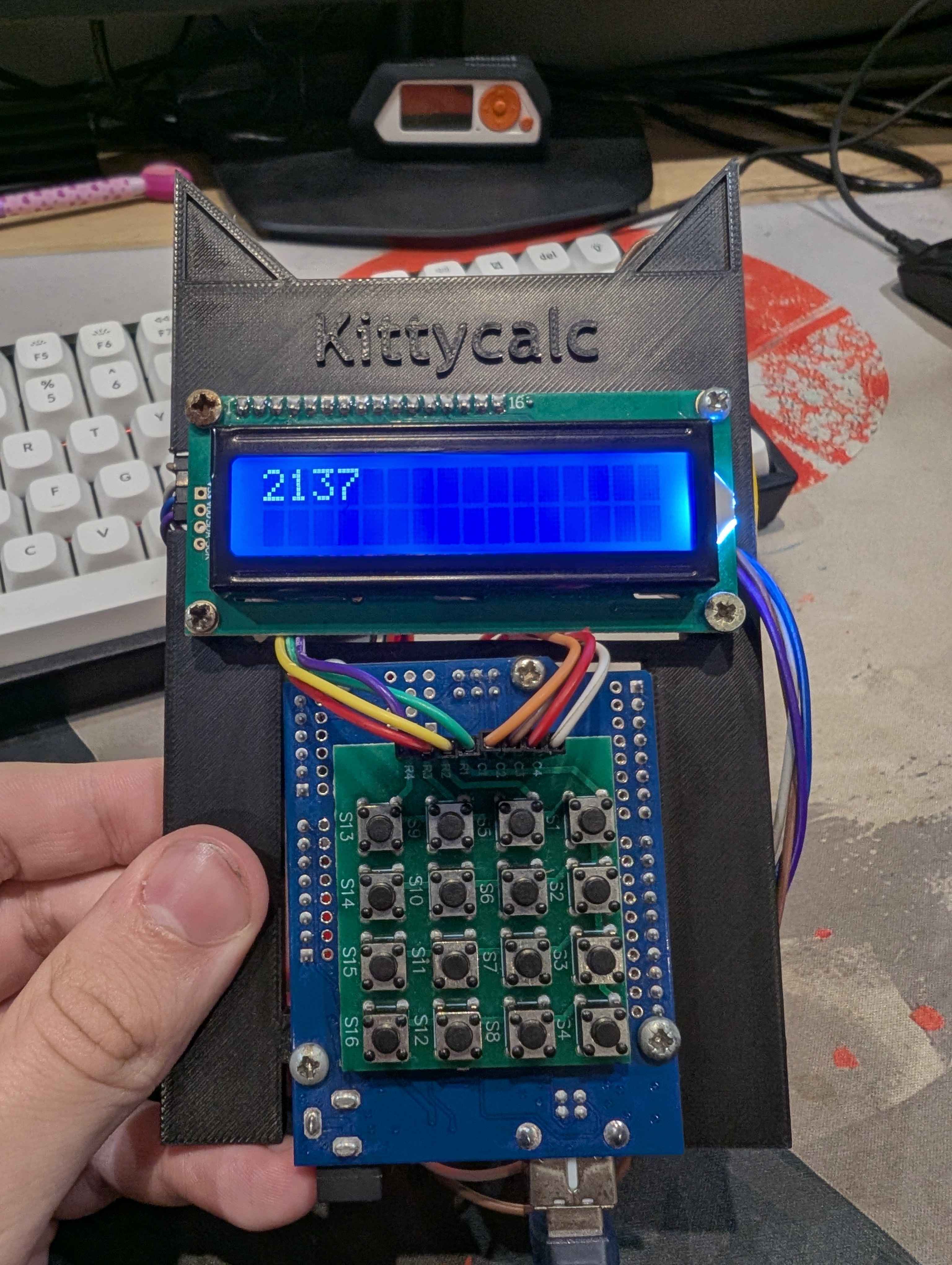 Enclosure in CAD
First Prototype
Enclosure in CAD
First Prototype
How it works
This project steps away from the standard Arduino (.ino) environment and relies on bare-metal C99 programming (AVR libc) to maximize performance and demonstrate what happens under the hood.
- Logic (FSM): The calculator logic isn't a messy
if/elseblock inmain.c. It's decoupled intocalculator.cand operates as a Finite State Machine (FSM) with an accumulator and a display register, mimicking real Casio chips. - Hardware Debouncing: Keypad inputs are heavily debounced in software (20ms delay logic on state change) directly in the scanning matrix, effectively ignoring both press-bounce and the notoriously tricky release-bounce.
- Direct Register Access: Uses direct port manipulation (
PORTC,PORTD, etc.) instead of slowdigitalWrite()wrappers for keypad scanning.
Wiring
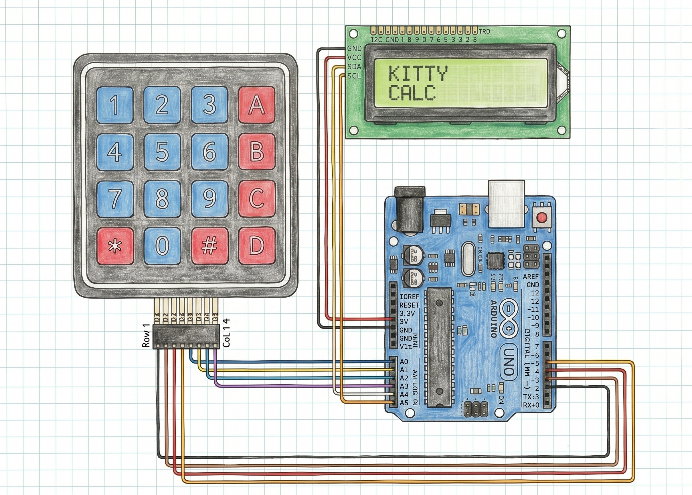
The project uses an I2C module for the LCD to save pins, leaving enough GPIOs for the 4x4 matrix keypad.
| Component / Pin | ATmega328P (Arduino Uno) Pin |
|---|---|
| I2C LCD SDA | A4 (PC4) |
| I2C LCD SCL | A5 (PC5) |
| I2C LCD VCC | 5V |
| I2C LCD GND | GND |
| Keypad Row 1 | D2 (PD2) |
| Keypad Row 2 | D3 (PD3) |
| Keypad Row 3 | D4 (PD4) |
| Keypad Row 4 | D5 (PD5) |
| Keypad Col 1 | A0 (PC0) |
| Keypad Col 2 | A1 (PC1) |
| Keypad Col 3 | A2 (PC2) |
| Keypad Col 4 | A3 (PC3) |
[Add a wiring diagram image — make one in Fritzing or annotate a clear photo:]
Firmware
This project is written in pure C. The logic is divided into modular files:
main.c- The system router.calculator.c- FSM calculator logic.lcd_i2c.c- Custom bare-metal I2C driver for the display.keypad.c- Matrix scanning and debouncing.
To flash it, you can use avr-gcc with avrdude, or simply open the project in PlatformIO / Microchip Studio and hit upload.
Bill of Materials (BOM)
| # | Part | Qty | Link | Approx. price |
|---|---|---|---|---|
| 1 | Arduino Uno (used as dev board) | 1 | link | ~20zł |
| 2 | 4x4 matrix keypad | 1 | link | ~12zł |
| 3 | 16x2 character LCD (with I2C backpack) | 1 | link | ~25zł |
| 4 | Jumper wires (M-M / M-F) | ~15 | link | ~30zł |
| 5 | Random screws | 8 | [link] | FREE |
| 6 | 3D-printed enclosure | 1 | cad/ | filament |
Build notes
When I started building this project, I thought it was going to be easy—until I learned how hard it is to write raw asm bare-metal code for an LCD display originally designed for 16 parallel pins! That was the moment I switched my approach, utilized an I2C backpack, and structured the whole system in clean C99.
Another huge learning curve was physics: mechanical switch bouncing. Writing a custom matrix scanner that properly filters out both press and release noise without lagging the CPU was a major milestone for this build.
License
MIT License. Feel free to use the code and CAD files for your own desk companions!
Similar repos


Languages
C
72.3%
Assembly
22.3%
Makefile
5.3%
See what people are saying
README
Kitty Calculator
A small desk companion — a calculator built entirely from scratch in pure C99 for the ATmega328P.
What it does
Works like a normal calculator but with a dangerously-cute looking style
Demo
Photos
Enclosure in CAD
First Prototype
How it works
This project steps away from the standard Arduino (.ino) environment and relies on bare-metal C99 programming (AVR libc) to maximize performance and demonstrate what happens under the hood.
- Logic (FSM): The calculator logic isn't a messy
if/elseblock inmain.c. It's decoupled intocalculator.cand operates as a Finite State Machine (FSM) with an accumulator and a display register, mimicking real Casio chips. - Hardware Debouncing: Keypad inputs are heavily debounced in software (20ms delay logic on state change) directly in the scanning matrix, effectively ignoring both press-bounce and the notoriously tricky release-bounce.
- Direct Register Access: Uses direct port manipulation (
PORTC,PORTD, etc.) instead of slowdigitalWrite()wrappers for keypad scanning.
Wiring
The project uses an I2C module for the LCD to save pins, leaving enough GPIOs for the 4x4 matrix keypad.
| Component / Pin | ATmega328P (Arduino Uno) Pin |
|---|---|
| I2C LCD SDA | A4 (PC4) |
| I2C LCD SCL | A5 (PC5) |
| I2C LCD VCC | 5V |
| I2C LCD GND | GND |
| Keypad Row 1 | D2 (PD2) |
| Keypad Row 2 | D3 (PD3) |
| Keypad Row 3 | D4 (PD4) |
| Keypad Row 4 | D5 (PD5) |
| Keypad Col 1 | A0 (PC0) |
| Keypad Col 2 | A1 (PC1) |
| Keypad Col 3 | A2 (PC2) |
| Keypad Col 4 | A3 (PC3) |
[Add a wiring diagram image — make one in Fritzing or annotate a clear photo:]
Firmware
This project is written in pure C. The logic is divided into modular files:
main.c- The system router.calculator.c- FSM calculator logic.lcd_i2c.c- Custom bare-metal I2C driver for the display.keypad.c- Matrix scanning and debouncing.
To flash it, you can use avr-gcc with avrdude, or simply open the project in PlatformIO / Microchip Studio and hit upload.
Bill of Materials (BOM)
| # | Part | Qty | Link | Approx. price |
|---|---|---|---|---|
| 1 | Arduino Uno (used as dev board) | 1 | link | ~20zł |
| 2 | 4x4 matrix keypad | 1 | link | ~12zł |
| 3 | 16x2 character LCD (with I2C backpack) | 1 | link | ~25zł |
| 4 | Jumper wires (M-M / M-F) | ~15 | link | ~30zł |
| 5 | Random screws | 8 | [link] | FREE |
| 6 | 3D-printed enclosure | 1 | cad/ | filament |
Build notes
When I started building this project, I thought it was going to be easy—until I learned how hard it is to write raw asm bare-metal code for an LCD display originally designed for 16 parallel pins! That was the moment I switched my approach, utilized an I2C backpack, and structured the whole system in clean C99.
Another huge learning curve was physics: mechanical switch bouncing. Writing a custom matrix scanner that properly filters out both press and release noise without lagging the CPU was a major milestone for this build.
License
MIT License. Feel free to use the code and CAD files for your own desk companions!
Similar repos
Languages
C
72.3%
Assembly
22.3%
Makefile
5.3%