
A free, open source, mixed-signal circuit simulator that runs entirely in your browser. Rust engine compiled to WebAssembly, Svelte front end.
TypeScript
7
223 commits
updated Sep 25, 2026
See what people are saying
README
repath
A free, open source, mixed-signal circuit simulator that runs entirely in your browser.



Try it — nothing to install, and nothing leaves your machine: the engine is WebAssembly and the whole simulation runs in the tab.
Analog and digital in the same schematic. Draw a comparator into a NAND gate and it works — repath figures out where the two domains meet and inserts the converters itself.
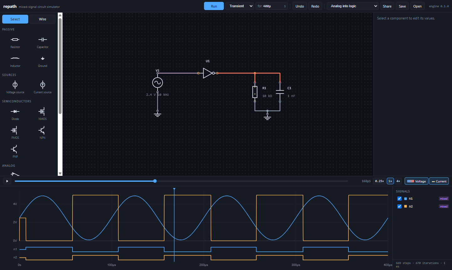
A 10 kHz sine into a logic inverter, its output filtered by an RC. One schematic, both domains, no converters placed by hand.
- MIT licensed. Every feature, no accounts, no paywall.
- No server. The engine is WebAssembly; your circuits never leave your machine.
- Real SPICE-class analysis. Modified nodal analysis, Newton-Raphson, companion models, adaptive timestepping, and the convergence aids that make nonlinear circuits actually solve.
- You can watch it work. Wires coloured by voltage and current animated along them, derived from the simulation rather than decorated on top of it.
- Shareable. The whole circuit fits in a URL, so a link is a working circuit.
Contents
- Status · Running it · How it works
- What is in the box · Using the editor
- Roadmap · Testing · Contributing
- CHANGELOG.md — what changed, from the user's side
Status
Usable, and honest about what it does. The engine handles DC, transient, AC and mixed-signal, and every claim in this file is covered by a test that checks the answer against something derived independently. What is not here yet — a sparse solver, noise and distortion analysis, MOSFET models past Shichman-Hodges — is in the Roadmap rather than half-implemented.
Running it
You need Rust, Node 20+, and
wasm-pack (cargo install wasm-pack).
git clone https://github.com/Agustin-Delgado/repath.git
cd repath

# Build the engine into the web app
wasm-pack build crates/repath-wasm --release --target web \
  --out-dir ../../web/src/lib/wasm --out-name repath

cd web
npm install
npm run dev
The production build is fully static — npm run build produces a directory you can
drop on any host.
How it works
crates/repath-core    the simulation engine (pure Rust, no web dependencies)
crates/repath-wasm    WebAssembly bindings
web/src/lib/canvas    2D editor engine — viewport, layers, spatial index, tools
web/src/lib/schematic the circuit-specific half: symbols, netlist, drawing, tools
web                   SvelteKit shell, scope, component palette
The analog side
Every element stamps its contribution into a matrix — this is modified nodal analysis. Node voltages are the unknowns, plus one extra unknown per element that defines a voltage rather than a current (sources, inductors, op-amps).
Nonlinear devices are linearized around the current guess and the system is solved again, repeatedly, until the answer stops moving. Diodes, BJTs and MOSFETs all compute their terminal currents and the derivatives of those currents, which is what Newton-Raphson needs.
Capacitors and inductors become companion models: at each timestep a capacitor is replaced by a conductance in parallel with a current source carrying its history. That is what turns a differential equation into the linear system the solver already knows how to handle. The default rule is trapezoidal, which is second order and adds no numerical damping, with backward Euler for the first steps and after any discontinuity — otherwise the trapezoidal rule rings.
Convergence
This is where simulators are actually judged. Three fallbacks run in order:
- Plain Newton from the last known solution.
- gmin stepping — a large conductance is added from every node to ground, making the circuit trivially solvable, then walked down decade by decade with each solution seeding the next.
- Source stepping — every independent source is scaled to zero, where the answer is all zeros, and ramped back up.
Every exponential junction runs through SPICE's pnjlim voltage limiting first.
Without it a single overshooting iterate produces exp(500) and the solve dies.
Timestep control
Every charge in the circuit records itself at each accepted timepoint — a capacitor's,
an inductor's flux, a transistor's junction and gate capacitances, an op-amp's
compensation. The third divided difference of that history estimates the local
truncation error, and the solver takes the tightest step any of them asks for. That
is what makes the answer a property of the circuit rather than of the window it is
being watched through. Below a noise floor derived from floating-point precision the
estimate is ignored — a straight line's third divided difference is rounding error
amplified by 1/h³, and steering by it would collapse the timestep for no reason.
The loop never steps over a discontinuity. Before each step it takes the minimum of the error budget, the shortest feature of any source waveform, the next waveform corner, the next digital event, and the end of any digital-to-analog ramp in flight.
What it does not watch is a nonlinear device's conduction. Only stored charge is integrated, so only stored charge has a truncation error to estimate — which is true of every SPICE and is fine for a signal small beside a junction's 26 mV, where the default step already converges to five figures. Drive one hard and it does not: the harmonics that come back out of the exponential are shorter than anything the step controller can see, and the answer is under-resolved with nothing to say so. A large-signal run wants its step set by hand until that changes; BACKLOG.md has the measurement.
The frequency domain
AC analysis is a small-signal analysis. The operating point is solved first, every nonlinear device linearizes around it, and the sweep then describes how a small wiggle propagates — not what the circuit does when driven hard. An amplifier biased into cutoff correctly reports no gain, which is the whole point of doing it this way: the answer depends on the bias the circuit actually settled at.
Each frequency builds a complex matrix — a capacitor stamps jωC, an inductor
jωL, a transistor the conductances it computed at the operating point — and
solves it. Phase is unwrapped afterwards, so a two-pole rolloff walks past −180°
instead of teleporting to +180° in the middle of the plot.
Set one source's AC drive to 1 to make it the input; everything else supplies bias only.
The digital side
Nothing steps through time. Devices run only when an input changes, and schedule their outputs into the future by their propagation delay. A 100 MHz clock feeding an idle counter costs a handful of evaluations per cycle, not one per analog timestep.
Nets are four-state (0, 1, X, Z) and multiply driven on purpose, so tri-state
buses resolve properly and contention shows up as X instead of silently picking a
winner.
Bridging the two
Neither side ever sees a discontinuity:
- A digital-to-analog bridge never jumps. When its net changes it ramps over a real rise or fall time, so the analog solver sees a continuous waveform and never has to re-solve a timepoint it already accepted.
- An analog-to-digital bridge watches a node between accepted timepoints and, when the voltage crosses a threshold, interpolates the crossing instant and schedules the digital event there rather than at the end of the step. Thresholds have hysteresis, so a slow edge produces one event rather than a burst.
The editor works out where a bridge is needed from the pins on each net. Analog pins and digital pins on the same wire means a bridge — in whichever direction the digital pins point.
The editor
The canvas is its own small engine (web/src/lib/canvas), deliberately ignorant of
circuits so it can be tested without a browser and reused for anything else.
Layered canvases. Grid, schematic, live overlay and tool feedback each get
their own canvas. Dragging a selection rectangle repaints only the top one; a
playing animation repaints only the live one; the schematic underneath — which
may hold thousands of components — is never re-rasterized for either. Nothing
repaints at all until something calls invalidate.
A spatial index. Every question the editor asks is a spatial one: what is on screen, what is under the cursor, what falls inside the marquee. A uniform grid hash keeps those proportional to the answer rather than to the document. Items carry a precise hit test alongside their bounding box, so a long diagonal wire is pickable along the wire and not across the empty rectangle around it.
Snapping, which is most of what separates precise from fiddly. Three things can be snapped to, in order of how much you probably meant them: pins, then anywhere along an existing wire, then the grid. The radius is a screen-pixel tolerance converted to world units, so the feel stays constant across zoom levels instead of getting stickier as you zoom in.
Wires are routed connections, not loose segments. A wire is a polyline — one thing you drew, one thing you select, move and delete. That is what lets two things work that otherwise cannot: dragging a component brings its wires with it and re-routes them, instead of leaving them behind holding nothing; and dragging off a pin draws a connection without switching tools, which is the gesture people reach for after dropping a part.
Pressing a wire, though, means the wire. That used to be ambiguous — a click to select it, or the start of a branch off it — and the tool guessed by watching whether the pointer moved next, so a wire someone meant to drag ran away and became a new wire instead. Dragging a thing should move the thing, so branching has a tool of its own in the palette. It is the only thing that tool is for: a run off the middle of an existing wire is the one connection a pin cannot start.
Either way a wire needs something at both ends. One that would be left in mid-air is turned away as it is drawn, not after.
The router is A* over the grid, with costs rather than walls almost everywhere. Only component bodies are real obstacles; crossing a wire, running alongside one, and turning a corner are all expensive but possible, in that order — running along an existing wire is worst, because two conductors on the same line cannot be told apart. A router that refuses when the ideal path is blocked is worse than one that produces a slightly ugly wire, so it always returns something.
Tools as state machines. Select, wire and place are separate objects with a small protocol — pointer events in, overlay drawing out. None of them touches the DOM, which is what keeps the pointer handling from collapsing back into one function full of mode flags.
Text is drawn in screen space rather than scaled with the world: rasterizing a glyph and then magnifying it is what makes canvas text look muddy.
The live layer
A net has one voltage, so colouring wires by it is exact. Current is harder: the engine knows what flows through each device, but a wire is only a connection, and a net with several branches does not assign a current to each segment on its own.
It does once you look at the topology. Cut a wire in a tree-shaped net and the net falls into two halves; that wire must carry whatever is injected on one side. So each net gets a spanning tree, rooted at ground where there is one, and the device currents accumulate from the leaves inward. That is exact for trees, which nets nearly always are. Wires that close a loop are genuinely ambiguous — ideal wires in parallel share current in no defined ratio — and are left alone rather than guessed at.
Voltage uses a diverging scale: two hues with a neutral grey midpoint, no rainbow and no hue in the middle. Zero volts is drawn in the ordinary wire grey, so colour appears only where there is something to say. The poles were checked rather than eyeballed — ΔE 22 under protanopia, 32 under tritanopia, 32 with normal vision, all clearing 3:1 against the canvas — and colour is never the only channel, since the same values are on the scope and in the readout.
Everything in this layer is a function of the instant being shown and nothing else, with one exception: the current dots carry a phase that accumulates as simulated time passes, because motion cannot be read off a single frozen moment. That is the one thing that has to be told when the sweep stops, and it is — dots still crawling under a stopped clock would report a flow the readouts beside them call frozen.
LEDs light from the same currents. Brightness follows a power law rather than the current itself, since a fifth of the current still reads as about half the light, and an overdriven one blazes past full before it goes.
Whether it goes is decided in the engine, inside the transient loop, by an integrated dose rather than a threshold: a brief pulse at ten times rated is ordinary multiplexed operation, while twice rated held for a millisecond is fatal. Only accepted timepoints count toward the dose, so a step the solver tried and threw away contributes nothing, and the trapezoid between timepoints keeps a spike the circuit spent no time at from destroying a part that was never in danger.
Deciding it there rather than reading it off the finished waveforms is what makes the answer usable: a part that fails at 321 µs is open from 321 µs, and everything after that is the circuit without it. In the LED driver example the node above the burnt part steps from its forward drop straight to the rail, because nothing is drawing through the series resistor any more — which is exactly what the bench would show you.
What is in the box
| Passive | resistor, capacitor, inductor, switch you can click, ground, supply terminal |
| Sources | voltage and current, with DC / sine / pulse waveforms |
| Semiconductors | diode (five presets, one of them a zener), LED (five colours, lights and burns out), NMOS, PMOS, NPN, PNP |
| Analog | op-amp with finite gain, bandwidth, slew rate and rail saturation; voltage-controlled switch; VCVS; VCCS |
| Logic | AND, NAND, OR, NOR, XOR, XNOR — two to four inputs each — NOT, buffer, D flip-flop, tri-state buffer, clock, logic toggle |
| Imported | .model cards pasted onto a part, and .subckt definitions placed as one |
| Instruments | probe, scope with cursors and per-channel gain, Bode plot |
| Analyses | DC operating point, mixed-signal transient, AC frequency sweep |
Using the editor
| Place a part | pick it in the palette, or press / and type its name or number (7400, npn, cap) and Enter; then click the canvas — R turns the ghost before you drop it. The parts you used last wait at the top of the palette |
| Find anything | Ctrl+K — every part, every command and every example, by name, with its shortcut beside it |
| Connect two things | drag from one pin to another — no tool to switch to first |
| Branch off a wire | pick Wire in the palette (or press W) and drag from any point on one |
| Move a wire | drag it; a leg with corners reshapes, a straight one slides |
| Place several of a part | hold Shift — otherwise the cursor comes back after one |
| Report something odd | File → Copy the steps taken copies everything you did, as text, so it can be replayed exactly |
| Save / open a file | Ctrl+S / Ctrl+O, or the File menu |
| Hand-route a wire | hold Shift while drawing to bypass the router |
| Reshape a wire | select it, then drag the leg you want to move |
| Select | click, Shift-click or Ctrl-click to add or remove one, or drag a box around things |
| Rotate / delete | R / Del |
| Pan | middle-drag, or Alt-drag |
| Zoom | scroll — Shift-scroll pans sideways |
| Fit to the drawing | F |
| Back to selecting | V or Esc |
| Copy / cut / paste | Ctrl+C / Ctrl+X / Ctrl+V — paste lands at the cursor |
| Duplicate | Ctrl+D |
| Group / ungroup | G / U (also Ctrl+G / Ctrl+Shift+G), or the buttons in the inspector — the group's name is its handle: click it to select the group, drag it to move the group, double-click it to rename |
| Box up / open up | B boxes the selected parts (or group) up as a block — one part with a pin per net that left them; U on a block opens it back up into the drawing. Rename the block and its ports in the inspector; place more copies from the palette. A pasted or duplicated box is a block of its own; one placed from the palette is the same block again, and Make its own block in the inspector parts them |
| Edit a block inside | double-click the box, or Edit inside in the inspector — the canvas becomes the block, every copy follows; wire a pin to a Port to give the box a pin; Back to the drawing when done |
| Undo / redo | Ctrl+Z / Ctrl+Shift+Z |
| Run / stop the sweep | Space |
| Simulate | press Run — nothing runs until you ask |
| Plot a net | type its name under Add a signal beside the scope; the × on a plotted one takes it off |
| Read it in your own symbols | the ANSI / IEC / GOST selector in the toolbar — zigzag or box resistors, shaped or boxed gates, an EMF drawn with an arrow |
Nothing simulates on load. Press Run and the simulation starts and keeps going, the way an instrument does: simulated time moves forward, the scope rolls, and the drawing shows the newest instant. There is no scrubber, because a running acquisition has nothing to scrub — Stop freezes what was caught, and only then can the window be dragged and zoomed over what memory still holds. Single sweeps one window and stops at the end of it, and Resume carries a stopped sweep on from where it got to — Run always starts again from zero.
Clicking a switch or a logic toggle while it is running operates it now: the engine is carried on from where it was, so everything already solved stays solved and the waveform gets the edge at the instant of the click. Change a value instead and the sweep restarts from zero — a different circuit is a different run. Moving a part around does not count as a change, since the circuit it describes has not changed.
A wire has to land on something at both ends — a pin, or another wire. A run that would finish in mid-air is drawn in red as you make it and declined on release, because in a simulator a free end conducts nothing.
Wires and pins snap: aim near a pin and the endpoint lands on it exactly, with the pin's name shown so you can see what you are about to connect to. Dragging a part until one of its pins is near another's snaps them together, so two components can be joined without a wire between them. Hovering highlights the whole net, not just the segment under the cursor.
Moving keeps connections. A dragged component brings its wires along and they re-route; a dragged wire stays plugged into whatever it was plugged into and grows legs to reach. The shape you see mid-drag is the shape you get on release — the same router runs in both cases, so nothing rearranges itself when you let go.
And moving never makes connections you did not ask for. A re-routed wire goes round every pin and every corner of every other wire, however far the detour; when no such route can be found it comes out as one straight leg from pin to pin, which joins nothing on the way and is plainly waiting to be tidied, rather than as an elbow through a row of pins. What the router cannot prevent — a pin coming down on a wire as a part turns, or grazing one as it is dragged past — is caught afterwards: what was joined to what is compared before and after, and a turn or a drop that would change it is undone with a notice saying what it would have joined. A pin dropped onto another pin, or onto the end of a wire, is the join the snap dot announced and goes through. Deleting a part takes the wires that led only to it, back to the last junction still doing something: a probe leaves nothing behind.
A group is a name over a handful of parts, the way a design tool groups shapes: a dashed frame around them with the name in the corner, drawn from wherever the parts are. The name is the handle. Clicking it takes the group, so it moves, turns and deletes as one; dragging it moves the group; double-clicking it renames it. A part is only ever picked on its own, so the group is never in the way of editing what is in it — and a part dragged clear of the frame has left the group. Groups travel in links and files. A group is not a subcircuit — the parts stay on the drawing, wired to whatever they are wired to — and groups do not nest.
A block is the next step: a piece of the drawing boxed up as a part of its own.
Select the parts — or the group — and press B, and they are replaced by one box
with a pin for every net that reached in from outside, named for the pin it came
from, inputs on the left and outputs on the right; an output nothing was wired to
yet gets a pin too, because it is still an output. The circuit simulates exactly
as before, because the engine never sees the box: it sees the parts inside, under
names like B1.U3. The block joins the palette, so a counter stage or a gain
block drawn once can be placed as many times as it is needed.
A block's terminals are the ports inside it: a wire from a pin to a port makes
that pin a pin on the box, under the port's name, on the side the port's flow
says. Double-click a box (or Edit inside) and the canvas becomes the block —
its parts, wires and ports, with the drawing waiting behind it — so a stage the
size of a page is edited on its own rather than unfolded into the middle of
everything. Add a port and the box grows a pin; delete one and the pin goes;
rename one and every copy follows, wires and all. Back to the drawing when
done. U still opens a block up into the drawing itself, as a group under the
block's name; box them up again and the block is updated. Blocks nest, and travel
in links and files with the drawing.
A box pasted or duplicated is a block of its own, numbered after the original — a "Second Hand" copied to draw the minute hand from is "Second Hand 2" until it is renamed, and renaming or editing it touches nothing else. A box placed from the palette is the same block again, the way two 7400s are the same chip: rename it or edit it inside and every copy changes. When one of those is wanted apart after all, select it and Make its own block in the inspector.
The symbol standard is the reader's, not the drawing's. A resistor is the same resistor whether it is drawn as a zigzag or a box, so the choice is not in a share link or a saved file: someone opening your link in another country sees it in the symbols they learnt, and the browser remembers yours. Pins never move between standards, so switching changes nothing about what is connected to what.
Values are a number and a scale, side by side, so digits and letters never share
a box. The arrow keys nudge the number and apply it as they go — Shift for ten
at a time, Alt for a tenth — and it settles into the right decade on its own, so
1 kΩ steps down to 999 Ω rather than to nothing. Typing engineering notation
still works if that is the habit you have: 4k7, 10u, 1meg, 100n.
The device-physics values — a saturation current, a junction capacitance, a gate delay — sit under More settings, so the value everyone sets is not one field among eight. The fold says how many of them were changed, so a folded change is not a hidden one.
Roadmap
The full list — including every known limitation and what is deliberately out of scope — is in BACKLOG.md. The headlines, roughly in order of how much they would change what repath is good for:
- Sparse matrix solver. The dense LU is fine to a few hundred nodes and then it is not.
- Drawn subcircuits. One pasted from a file is a part today; drawing a block once and nesting it is not.
- Dirty-rectangle repaint. Layer-level invalidation plus viewport culling covers most of the benefit today; per-region repaint is the next step up.
- Noise and distortion analysis, once AC has proved itself.
- Netlist import/export in SPICE format.
- Richer device models — MOSFET levels beyond Shichman-Hodges, and a BJT with high-level injection in it. The Early effect, channel-length modulation, the junction and gate capacitances and a diode's series resistance are all in, which is what gives a stage a top end and a rectifier a recovery.
- More logic: counters, registers, decoders, memory.
Testing
cargo test --workspace     # engine
cd web && npm test         # canvas engine
cd web && npm run check    # types
The suite itself is kept in a private repository, mounted here as the submodule
tests/; a clone of this one has the code and not the tests, and the two
commands above need the mount. CI runs the whole suite on every push and on
pull requests from this repository, and checks what it can — formatting, lints,
types and the build — on pull requests from a fork.
The engine's integration tests check circuits against answers derived independently: RC and RL step responses against the closed-form exponential, an LC tank against conservation of energy, a MOSFET's saturation current against the Shichman-Hodges equation, a BJT's operating point against hand analysis, and a NAND gate's output against its truth table at every sampled instant.
The frequency-domain tests are the same idea: an RC low-pass has to be −3 dB and exactly −45° at its corner, roll off 20 dB per decade, and settle at −90°; a series RLC has to peak at its resonant frequency with the Q its component values imply; and a common-emitter amplifier has to lose its gain when its base bias is taken away — which only happens if the sweep really is linearizing around the operating point.
Contributing
Issues and pull requests welcome — see CONTRIBUTING.md for how the project is laid out, what the tests expect, and the one rule that matters most here: a wrong answer delivered confidently is worse than no answer, so anything touching the engine needs a test that checks it against something derived independently.
The engine is deliberately independent of the web app — repath-core is a normal
Rust crate with no web dependencies, so it can be used on its own or wrapped in a
different front end.
If you are looking for somewhere to start, BACKLOG.md is the whole list, sorted, with the reasoning for each item and an honest table of what is deliberately simplified.
Licence
MIT. See LICENSE.
Similar repos



Languages
TypeScript
59.8%
Rust
26.7%
Svelte
13.3%
A free, open source, mixed-signal circuit simulator that runs entirely in your browser. Rust engine compiled to WebAssembly, Svelte front end.
TypeScript
7
223 commits
updated Sep 25, 2026
See what people are saying
README
repath
A free, open source, mixed-signal circuit simulator that runs entirely in your browser.
Try it — nothing to install, and nothing leaves your machine: the engine is WebAssembly and the whole simulation runs in the tab.
Analog and digital in the same schematic. Draw a comparator into a NAND gate and it works — repath figures out where the two domains meet and inserts the converters itself.
A 10 kHz sine into a logic inverter, its output filtered by an RC. One schematic, both domains, no converters placed by hand.
- MIT licensed. Every feature, no accounts, no paywall.
- No server. The engine is WebAssembly; your circuits never leave your machine.
- Real SPICE-class analysis. Modified nodal analysis, Newton-Raphson, companion models, adaptive timestepping, and the convergence aids that make nonlinear circuits actually solve.
- You can watch it work. Wires coloured by voltage and current animated along them, derived from the simulation rather than decorated on top of it.
- Shareable. The whole circuit fits in a URL, so a link is a working circuit.
Contents
- Status · Running it · How it works
- What is in the box · Using the editor
- Roadmap · Testing · Contributing
- CHANGELOG.md — what changed, from the user's side
Status
Usable, and honest about what it does. The engine handles DC, transient, AC and mixed-signal, and every claim in this file is covered by a test that checks the answer against something derived independently. What is not here yet — a sparse solver, noise and distortion analysis, MOSFET models past Shichman-Hodges — is in the Roadmap rather than half-implemented.
Running it
You need Rust, Node 20+, and
wasm-pack (cargo install wasm-pack).
git clone https://github.com/Agustin-Delgado/repath.git
cd repath

# Build the engine into the web app
wasm-pack build crates/repath-wasm --release --target web \
  --out-dir ../../web/src/lib/wasm --out-name repath

cd web
npm install
npm run dev
The production build is fully static — npm run build produces a directory you can
drop on any host.
How it works
crates/repath-core    the simulation engine (pure Rust, no web dependencies)
crates/repath-wasm    WebAssembly bindings
web/src/lib/canvas    2D editor engine — viewport, layers, spatial index, tools
web/src/lib/schematic the circuit-specific half: symbols, netlist, drawing, tools
web                   SvelteKit shell, scope, component palette
The analog side
Every element stamps its contribution into a matrix — this is modified nodal analysis. Node voltages are the unknowns, plus one extra unknown per element that defines a voltage rather than a current (sources, inductors, op-amps).
Nonlinear devices are linearized around the current guess and the system is solved again, repeatedly, until the answer stops moving. Diodes, BJTs and MOSFETs all compute their terminal currents and the derivatives of those currents, which is what Newton-Raphson needs.
Capacitors and inductors become companion models: at each timestep a capacitor is replaced by a conductance in parallel with a current source carrying its history. That is what turns a differential equation into the linear system the solver already knows how to handle. The default rule is trapezoidal, which is second order and adds no numerical damping, with backward Euler for the first steps and after any discontinuity — otherwise the trapezoidal rule rings.
Convergence
This is where simulators are actually judged. Three fallbacks run in order:
- Plain Newton from the last known solution.
- gmin stepping — a large conductance is added from every node to ground, making the circuit trivially solvable, then walked down decade by decade with each solution seeding the next.
- Source stepping — every independent source is scaled to zero, where the answer is all zeros, and ramped back up.
Every exponential junction runs through SPICE's pnjlim voltage limiting first.
Without it a single overshooting iterate produces exp(500) and the solve dies.
Timestep control
Every charge in the circuit records itself at each accepted timepoint — a capacitor's,
an inductor's flux, a transistor's junction and gate capacitances, an op-amp's
compensation. The third divided difference of that history estimates the local
truncation error, and the solver takes the tightest step any of them asks for. That
is what makes the answer a property of the circuit rather than of the window it is
being watched through. Below a noise floor derived from floating-point precision the
estimate is ignored — a straight line's third divided difference is rounding error
amplified by 1/h³, and steering by it would collapse the timestep for no reason.
The loop never steps over a discontinuity. Before each step it takes the minimum of the error budget, the shortest feature of any source waveform, the next waveform corner, the next digital event, and the end of any digital-to-analog ramp in flight.
What it does not watch is a nonlinear device's conduction. Only stored charge is integrated, so only stored charge has a truncation error to estimate — which is true of every SPICE and is fine for a signal small beside a junction's 26 mV, where the default step already converges to five figures. Drive one hard and it does not: the harmonics that come back out of the exponential are shorter than anything the step controller can see, and the answer is under-resolved with nothing to say so. A large-signal run wants its step set by hand until that changes; BACKLOG.md has the measurement.
The frequency domain
AC analysis is a small-signal analysis. The operating point is solved first, every nonlinear device linearizes around it, and the sweep then describes how a small wiggle propagates — not what the circuit does when driven hard. An amplifier biased into cutoff correctly reports no gain, which is the whole point of doing it this way: the answer depends on the bias the circuit actually settled at.
Each frequency builds a complex matrix — a capacitor stamps jωC, an inductor
jωL, a transistor the conductances it computed at the operating point — and
solves it. Phase is unwrapped afterwards, so a two-pole rolloff walks past −180°
instead of teleporting to +180° in the middle of the plot.
Set one source's AC drive to 1 to make it the input; everything else supplies bias only.
The digital side
Nothing steps through time. Devices run only when an input changes, and schedule their outputs into the future by their propagation delay. A 100 MHz clock feeding an idle counter costs a handful of evaluations per cycle, not one per analog timestep.
Nets are four-state (0, 1, X, Z) and multiply driven on purpose, so tri-state
buses resolve properly and contention shows up as X instead of silently picking a
winner.
Bridging the two
Neither side ever sees a discontinuity:
- A digital-to-analog bridge never jumps. When its net changes it ramps over a real rise or fall time, so the analog solver sees a continuous waveform and never has to re-solve a timepoint it already accepted.
- An analog-to-digital bridge watches a node between accepted timepoints and, when the voltage crosses a threshold, interpolates the crossing instant and schedules the digital event there rather than at the end of the step. Thresholds have hysteresis, so a slow edge produces one event rather than a burst.
The editor works out where a bridge is needed from the pins on each net. Analog pins and digital pins on the same wire means a bridge — in whichever direction the digital pins point.
The editor
The canvas is its own small engine (web/src/lib/canvas), deliberately ignorant of
circuits so it can be tested without a browser and reused for anything else.
Layered canvases. Grid, schematic, live overlay and tool feedback each get
their own canvas. Dragging a selection rectangle repaints only the top one; a
playing animation repaints only the live one; the schematic underneath — which
may hold thousands of components — is never re-rasterized for either. Nothing
repaints at all until something calls invalidate.
A spatial index. Every question the editor asks is a spatial one: what is on screen, what is under the cursor, what falls inside the marquee. A uniform grid hash keeps those proportional to the answer rather than to the document. Items carry a precise hit test alongside their bounding box, so a long diagonal wire is pickable along the wire and not across the empty rectangle around it.
Snapping, which is most of what separates precise from fiddly. Three things can be snapped to, in order of how much you probably meant them: pins, then anywhere along an existing wire, then the grid. The radius is a screen-pixel tolerance converted to world units, so the feel stays constant across zoom levels instead of getting stickier as you zoom in.
Wires are routed connections, not loose segments. A wire is a polyline — one thing you drew, one thing you select, move and delete. That is what lets two things work that otherwise cannot: dragging a component brings its wires with it and re-routes them, instead of leaving them behind holding nothing; and dragging off a pin draws a connection without switching tools, which is the gesture people reach for after dropping a part.
Pressing a wire, though, means the wire. That used to be ambiguous — a click to select it, or the start of a branch off it — and the tool guessed by watching whether the pointer moved next, so a wire someone meant to drag ran away and became a new wire instead. Dragging a thing should move the thing, so branching has a tool of its own in the palette. It is the only thing that tool is for: a run off the middle of an existing wire is the one connection a pin cannot start.
Either way a wire needs something at both ends. One that would be left in mid-air is turned away as it is drawn, not after.
The router is A* over the grid, with costs rather than walls almost everywhere. Only component bodies are real obstacles; crossing a wire, running alongside one, and turning a corner are all expensive but possible, in that order — running along an existing wire is worst, because two conductors on the same line cannot be told apart. A router that refuses when the ideal path is blocked is worse than one that produces a slightly ugly wire, so it always returns something.
Tools as state machines. Select, wire and place are separate objects with a small protocol — pointer events in, overlay drawing out. None of them touches the DOM, which is what keeps the pointer handling from collapsing back into one function full of mode flags.
Text is drawn in screen space rather than scaled with the world: rasterizing a glyph and then magnifying it is what makes canvas text look muddy.
The live layer
A net has one voltage, so colouring wires by it is exact. Current is harder: the engine knows what flows through each device, but a wire is only a connection, and a net with several branches does not assign a current to each segment on its own.
It does once you look at the topology. Cut a wire in a tree-shaped net and the net falls into two halves; that wire must carry whatever is injected on one side. So each net gets a spanning tree, rooted at ground where there is one, and the device currents accumulate from the leaves inward. That is exact for trees, which nets nearly always are. Wires that close a loop are genuinely ambiguous — ideal wires in parallel share current in no defined ratio — and are left alone rather than guessed at.
Voltage uses a diverging scale: two hues with a neutral grey midpoint, no rainbow and no hue in the middle. Zero volts is drawn in the ordinary wire grey, so colour appears only where there is something to say. The poles were checked rather than eyeballed — ΔE 22 under protanopia, 32 under tritanopia, 32 with normal vision, all clearing 3:1 against the canvas — and colour is never the only channel, since the same values are on the scope and in the readout.
Everything in this layer is a function of the instant being shown and nothing else, with one exception: the current dots carry a phase that accumulates as simulated time passes, because motion cannot be read off a single frozen moment. That is the one thing that has to be told when the sweep stops, and it is — dots still crawling under a stopped clock would report a flow the readouts beside them call frozen.
LEDs light from the same currents. Brightness follows a power law rather than the current itself, since a fifth of the current still reads as about half the light, and an overdriven one blazes past full before it goes.
Whether it goes is decided in the engine, inside the transient loop, by an integrated dose rather than a threshold: a brief pulse at ten times rated is ordinary multiplexed operation, while twice rated held for a millisecond is fatal. Only accepted timepoints count toward the dose, so a step the solver tried and threw away contributes nothing, and the trapezoid between timepoints keeps a spike the circuit spent no time at from destroying a part that was never in danger.
Deciding it there rather than reading it off the finished waveforms is what makes the answer usable: a part that fails at 321 µs is open from 321 µs, and everything after that is the circuit without it. In the LED driver example the node above the burnt part steps from its forward drop straight to the rail, because nothing is drawing through the series resistor any more — which is exactly what the bench would show you.
What is in the box
| Passive | resistor, capacitor, inductor, switch you can click, ground, supply terminal |
| Sources | voltage and current, with DC / sine / pulse waveforms |
| Semiconductors | diode (five presets, one of them a zener), LED (five colours, lights and burns out), NMOS, PMOS, NPN, PNP |
| Analog | op-amp with finite gain, bandwidth, slew rate and rail saturation; voltage-controlled switch; VCVS; VCCS |
| Logic | AND, NAND, OR, NOR, XOR, XNOR — two to four inputs each — NOT, buffer, D flip-flop, tri-state buffer, clock, logic toggle |
| Imported | .model cards pasted onto a part, and .subckt definitions placed as one |
| Instruments | probe, scope with cursors and per-channel gain, Bode plot |
| Analyses | DC operating point, mixed-signal transient, AC frequency sweep |
Using the editor
| Place a part | pick it in the palette, or press / and type its name or number (7400, npn, cap) and Enter; then click the canvas — R turns the ghost before you drop it. The parts you used last wait at the top of the palette |
| Find anything | Ctrl+K — every part, every command and every example, by name, with its shortcut beside it |
| Connect two things | drag from one pin to another — no tool to switch to first |
| Branch off a wire | pick Wire in the palette (or press W) and drag from any point on one |
| Move a wire | drag it; a leg with corners reshapes, a straight one slides |
| Place several of a part | hold Shift — otherwise the cursor comes back after one |
| Report something odd | File → Copy the steps taken copies everything you did, as text, so it can be replayed exactly |
| Save / open a file | Ctrl+S / Ctrl+O, or the File menu |
| Hand-route a wire | hold Shift while drawing to bypass the router |
| Reshape a wire | select it, then drag the leg you want to move |
| Select | click, Shift-click or Ctrl-click to add or remove one, or drag a box around things |
| Rotate / delete | R / Del |
| Pan | middle-drag, or Alt-drag |
| Zoom | scroll — Shift-scroll pans sideways |
| Fit to the drawing | F |
| Back to selecting | V or Esc |
| Copy / cut / paste | Ctrl+C / Ctrl+X / Ctrl+V — paste lands at the cursor |
| Duplicate | Ctrl+D |
| Group / ungroup | G / U (also Ctrl+G / Ctrl+Shift+G), or the buttons in the inspector — the group's name is its handle: click it to select the group, drag it to move the group, double-click it to rename |
| Box up / open up | B boxes the selected parts (or group) up as a block — one part with a pin per net that left them; U on a block opens it back up into the drawing. Rename the block and its ports in the inspector; place more copies from the palette. A pasted or duplicated box is a block of its own; one placed from the palette is the same block again, and Make its own block in the inspector parts them |
| Edit a block inside | double-click the box, or Edit inside in the inspector — the canvas becomes the block, every copy follows; wire a pin to a Port to give the box a pin; Back to the drawing when done |
| Undo / redo | Ctrl+Z / Ctrl+Shift+Z |
| Run / stop the sweep | Space |
| Simulate | press Run — nothing runs until you ask |
| Plot a net | type its name under Add a signal beside the scope; the × on a plotted one takes it off |
| Read it in your own symbols | the ANSI / IEC / GOST selector in the toolbar — zigzag or box resistors, shaped or boxed gates, an EMF drawn with an arrow |
Nothing simulates on load. Press Run and the simulation starts and keeps going, the way an instrument does: simulated time moves forward, the scope rolls, and the drawing shows the newest instant. There is no scrubber, because a running acquisition has nothing to scrub — Stop freezes what was caught, and only then can the window be dragged and zoomed over what memory still holds. Single sweeps one window and stops at the end of it, and Resume carries a stopped sweep on from where it got to — Run always starts again from zero.
Clicking a switch or a logic toggle while it is running operates it now: the engine is carried on from where it was, so everything already solved stays solved and the waveform gets the edge at the instant of the click. Change a value instead and the sweep restarts from zero — a different circuit is a different run. Moving a part around does not count as a change, since the circuit it describes has not changed.
A wire has to land on something at both ends — a pin, or another wire. A run that would finish in mid-air is drawn in red as you make it and declined on release, because in a simulator a free end conducts nothing.
Wires and pins snap: aim near a pin and the endpoint lands on it exactly, with the pin's name shown so you can see what you are about to connect to. Dragging a part until one of its pins is near another's snaps them together, so two components can be joined without a wire between them. Hovering highlights the whole net, not just the segment under the cursor.
Moving keeps connections. A dragged component brings its wires along and they re-route; a dragged wire stays plugged into whatever it was plugged into and grows legs to reach. The shape you see mid-drag is the shape you get on release — the same router runs in both cases, so nothing rearranges itself when you let go.
And moving never makes connections you did not ask for. A re-routed wire goes round every pin and every corner of every other wire, however far the detour; when no such route can be found it comes out as one straight leg from pin to pin, which joins nothing on the way and is plainly waiting to be tidied, rather than as an elbow through a row of pins. What the router cannot prevent — a pin coming down on a wire as a part turns, or grazing one as it is dragged past — is caught afterwards: what was joined to what is compared before and after, and a turn or a drop that would change it is undone with a notice saying what it would have joined. A pin dropped onto another pin, or onto the end of a wire, is the join the snap dot announced and goes through. Deleting a part takes the wires that led only to it, back to the last junction still doing something: a probe leaves nothing behind.
A group is a name over a handful of parts, the way a design tool groups shapes: a dashed frame around them with the name in the corner, drawn from wherever the parts are. The name is the handle. Clicking it takes the group, so it moves, turns and deletes as one; dragging it moves the group; double-clicking it renames it. A part is only ever picked on its own, so the group is never in the way of editing what is in it — and a part dragged clear of the frame has left the group. Groups travel in links and files. A group is not a subcircuit — the parts stay on the drawing, wired to whatever they are wired to — and groups do not nest.
A block is the next step: a piece of the drawing boxed up as a part of its own.
Select the parts — or the group — and press B, and they are replaced by one box
with a pin for every net that reached in from outside, named for the pin it came
from, inputs on the left and outputs on the right; an output nothing was wired to
yet gets a pin too, because it is still an output. The circuit simulates exactly
as before, because the engine never sees the box: it sees the parts inside, under
names like B1.U3. The block joins the palette, so a counter stage or a gain
block drawn once can be placed as many times as it is needed.
A block's terminals are the ports inside it: a wire from a pin to a port makes
that pin a pin on the box, under the port's name, on the side the port's flow
says. Double-click a box (or Edit inside) and the canvas becomes the block —
its parts, wires and ports, with the drawing waiting behind it — so a stage the
size of a page is edited on its own rather than unfolded into the middle of
everything. Add a port and the box grows a pin; delete one and the pin goes;
rename one and every copy follows, wires and all. Back to the drawing when
done. U still opens a block up into the drawing itself, as a group under the
block's name; box them up again and the block is updated. Blocks nest, and travel
in links and files with the drawing.
A box pasted or duplicated is a block of its own, numbered after the original — a "Second Hand" copied to draw the minute hand from is "Second Hand 2" until it is renamed, and renaming or editing it touches nothing else. A box placed from the palette is the same block again, the way two 7400s are the same chip: rename it or edit it inside and every copy changes. When one of those is wanted apart after all, select it and Make its own block in the inspector.
The symbol standard is the reader's, not the drawing's. A resistor is the same resistor whether it is drawn as a zigzag or a box, so the choice is not in a share link or a saved file: someone opening your link in another country sees it in the symbols they learnt, and the browser remembers yours. Pins never move between standards, so switching changes nothing about what is connected to what.
Values are a number and a scale, side by side, so digits and letters never share
a box. The arrow keys nudge the number and apply it as they go — Shift for ten
at a time, Alt for a tenth — and it settles into the right decade on its own, so
1 kΩ steps down to 999 Ω rather than to nothing. Typing engineering notation
still works if that is the habit you have: 4k7, 10u, 1meg, 100n.
The device-physics values — a saturation current, a junction capacitance, a gate delay — sit under More settings, so the value everyone sets is not one field among eight. The fold says how many of them were changed, so a folded change is not a hidden one.
Roadmap
The full list — including every known limitation and what is deliberately out of scope — is in BACKLOG.md. The headlines, roughly in order of how much they would change what repath is good for:
- Sparse matrix solver. The dense LU is fine to a few hundred nodes and then it is not.
- Drawn subcircuits. One pasted from a file is a part today; drawing a block once and nesting it is not.
- Dirty-rectangle repaint. Layer-level invalidation plus viewport culling covers most of the benefit today; per-region repaint is the next step up.
- Noise and distortion analysis, once AC has proved itself.
- Netlist import/export in SPICE format.
- Richer device models — MOSFET levels beyond Shichman-Hodges, and a BJT with high-level injection in it. The Early effect, channel-length modulation, the junction and gate capacitances and a diode's series resistance are all in, which is what gives a stage a top end and a rectifier a recovery.
- More logic: counters, registers, decoders, memory.
Testing
cargo test --workspace     # engine
cd web && npm test         # canvas engine
cd web && npm run check    # types
The suite itself is kept in a private repository, mounted here as the submodule
tests/; a clone of this one has the code and not the tests, and the two
commands above need the mount. CI runs the whole suite on every push and on
pull requests from this repository, and checks what it can — formatting, lints,
types and the build — on pull requests from a fork.
The engine's integration tests check circuits against answers derived independently: RC and RL step responses against the closed-form exponential, an LC tank against conservation of energy, a MOSFET's saturation current against the Shichman-Hodges equation, a BJT's operating point against hand analysis, and a NAND gate's output against its truth table at every sampled instant.
The frequency-domain tests are the same idea: an RC low-pass has to be −3 dB and exactly −45° at its corner, roll off 20 dB per decade, and settle at −90°; a series RLC has to peak at its resonant frequency with the Q its component values imply; and a common-emitter amplifier has to lose its gain when its base bias is taken away — which only happens if the sweep really is linearizing around the operating point.
Contributing
Issues and pull requests welcome — see CONTRIBUTING.md for how the project is laid out, what the tests expect, and the one rule that matters most here: a wrong answer delivered confidently is worse than no answer, so anything touching the engine needs a test that checks it against something derived independently.
The engine is deliberately independent of the web app — repath-core is a normal
Rust crate with no web dependencies, so it can be used on its own or wrapped in a
different front end.
If you are looking for somewhere to start, BACKLOG.md is the whole list, sorted, with the reasoning for each item and an honest table of what is deliberately simplified.
Licence
MIT. See LICENSE.
Similar repos
Languages
TypeScript
59.8%
Rust
26.7%
Svelte
13.3%